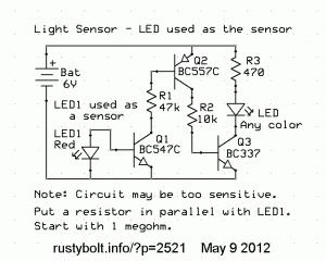
I watched this video on Youtube called Light Sensor Making Steps. He shows a schematic at the beginning. The problem is that when the light is bright, the CdS “LDR ” photocell’s resistance can go well below 1000 ohms, and then the photocell is passing as much or more current as the LED is using. The total current to the circuit is much more than the LED current, and it is very wasteful, especially if the circuit is being powered by a battery, which will be drained much faster.
So I thought I should come up with a better circuit  . And it doesn’t have to use a CdS photocell. Instead, it will use a red LED as a light sensor (see the schematic).
Another alternative solution is to put a resistor in series with the CdS photocell, to limit the amount of current it passes. The transistor needs only a fraction of a milliamp to turn on and light the red LED. I would say insert a 3.3k resistor in series with the photocell, and see how it works.
Also, remember that you do not have to source current through R2, you can sink current. Swap the Q1 and Q2 transistors. Put the BC557 first, with the cathode or flat spot of red LED connected to the base and the anode connected to +6V along with the BC557’s emitter. The BC557’s collector then connects to the 47k, which then connects to the BC547’s base.


