default

2012-04-25 Solar Cell As A LED

Quantsuff sent me a link to this article about researchers who found a new or different way to increase the efficiency of a solar cell – make it more like a LED.

I relate this experience  to demonstrate that there are technologies out there that are waiting to make a major change in how the world functions, but just haven’t yet been utilized.  Years ago I bought a small square or rectangle of a material that would allow one to test the output of an infrared LED.  It had to be ‘activated’ by exposing it to bright light, either close to a light bulb or the sunlight.  Then for a short period it would glow when an infrared LED was shone on it.

I haven’t seen this sort of thing for a long time.  But it would make sense that one could put the same chemicals into a solar photovoltaic cell, and when the wide band of sunlight hits it, the chemicals would first be activated by the visible light, then when the sunlight’s infrared hits it, it would re-emit the IR frequencies as visible light, and it would then be able to turn that light into electricity.  I may be wrong in trying to change the frequency of the light, because I am not sure how well the silicon solar cells convert IR itself into electricity, compared to visible light.  But the use of this chemical might be able to increase the efficiency of a solar cell.

In any case, in the link, the researchers have taken a new approach to the way a solar cell is designed to operate.  And this research is a step forward on the way to someday making us independent of non-renewable energy sources.

Another technique that I’ve seen is to increase the efficiency of a solar cell by gathering more sunlight and concentrating it on the cell.  The sun moves across the sky during the day, so the sunlight would go out of focus as it moves across the cell.  The solution is to move the solar cell or the whole array to point at the sun.  Ths adds to the complexity of the solar array; the array will need motors to drive it, and sensors to tell where the sun is at.

There may be a way to compromise and design a solar array that requires less or no movement, yet focuses the sun on an array that is somewhat bigger than a movable array, yet has some of the increased efficiency of a movable array.  For example, if the array had solar cells at three points of focus, and was designed to not move, it might be simple like a non-movable array, yet have higher efficiency.  And also, it’s important that it be cost effective.

I learned a few other things from this article.  They stated that the theoretical maximum efficiency of a solar cell is 33 percent.


default

2012-04-24 BioPhotoVoltaics – Moss Power

on April 24th, 2012 by - Comments Off on 2012-04-24 BioPhotoVoltaics – Moss Power

Quantsuff sent me a link to an article about a table that is used to grow moss and which furnishes a small amount of electricity.  It is in the research stage, so not enough power is generated to do anything more than power a small device such as a LED for a short while.  But it does have potential (no pun intended) to turn into a useful source of electricity.

The amount of electricity developed by each moss pot is minuscule, only a half volt at 5 to 10 microamps.  It would take several thousand in series-parallel to give enough current to light a LED to reasonable brightness.  I could see using this to do something in a location that has limited or no sunlight.  A small solar panel could put out thousands of times more power than this moss, but only during daylight hours.

I have seen some “Free Energy” fanatics discussing about how to make electricity from a tree.  They thought there would be enough to power a small device such as temperature / weather monitoring  equipment and power to be able to send the data periodically to a satellite or cell site.  I didn’t take it too seriously mainly because some environmentalists might take offense to draining their trees of electricity.  But maybe they could let the researchers play around with moss without complaining.

Update – Another link from QS, this one about a spinach powered solar cell.  It doesn’t sound serious, but the process of photosynthesis is a very efficient way to use the energy in sunlight to make biomass.  Also, I would like to point out one thing they said in the article: the very first sentence. I quote:

“Earth Day 2012 proved exceptionally green for a Vanderbilt University team of five engineering seniors who designed a biohybrid solar panel that substitutes a protein from spinach for expensive silicon wafers that are energy intensive to produce, and is capable of producing electricity.”

The key part is “expensive silicon wafers that are energy intensive to produce”.  People don’t realize that silicon solar cells take a lot of energy in the manufacturing process.  If the amount of energy it takes to make a solar cell is a substantial amount of the total energy it will convert in its lifetime, then one has to realize that it is not making totally renewable energy.  One has to include the amount of energy it took to manufacture into the total amount of energy it is putting out. Say for instance a solar cell puts out a million Joules of energy in its lifetime, but it took a half million Joules to produce, then it is really only 50% renewable energy when you look at the overall picture.  At the present time, almost all of the half million Joules of energy used to produce it was derived from non-renewable energy sources.

The same thing applies to any form of generation.  I believe that the nuclear power industry has large hidden costs incurred during production of the fuel.  Those centrifuges and other equipment used to enrich the fuel take a lot of power and may not be running on renewable energy.  And there are substantial costs to transporting, refueling and storing the fuel of the nuclear power plants.

These hidden costs must be accounted for in any renewable energy system.  If they are not, then we are not getting the true ‘renewableness’ of a supposedly renewable energy system.  And it also makes these biophotovoltaic solar cells look more attractive since they take less energy to produce.

I also believe that there needs to be more of an awareness of what is happening to our existing matter and energy that is being made from the sun.

default

2012-04-23 Electromagnetic Absorbing Material

on April 23rd, 2012 by - Comments Off on 2012-04-23 Electromagnetic Absorbing Material

I found this website that has some interesting info, including what to use for EM absorbing material.  He says to use magnetic recording tape.

default

2012-04-22 Power To The Proto Board

on April 22nd, 2012 by - Comments Off on 2012-04-22 Power To The Proto Board

I got an email from QS showing how he put the buck DC-DC downconverter right at the point where it plugs into the proto board.  This is really the way to go to eliminate any IR drops from the resistance of the leads.   There are two items which I am concerned about, one being the ripple current that may be coming out of the converter, and the other is if the proto board itself might have internal resistance that could cause IR drop.  One has to remember that when we are working with 15 volts output and the ripple is a half volt, the ripple is only 1/30th or 3.3% of the output voltage.  But when the output is 1.5V and the ripple is a half volt, the ripple is 1/3 or 33% of the output voltage – way too much!

I can address the first concern by using a linear regulator such as the LM317.  Two issues here that have to be dealt with, one is that it cannot go below 1.25VDC.  That’s okay for working with circuits designed to run on a single alkaline cell, but if the circuit is to work with a 1.2V rechargeable, then there has to be a way to go to a lower voltage.  I’ve thought about this, and I figured that a 5 or more amp Schottky rectifier in series with the line would drop about 1/4 to a half volt, but it would not be well regulated.  Another way would be to use a negative supply for the adjustment pot, but I have had major problems with this method.

The other issue with the LM317 is the limit on the current, generally 1 amp if it has a good heatsink, but less if the regulator gets too hot and shuts down.  I can reduce the input voltage to 5 volts, and it might be able to handle the full 1 amp current or maybe more without too much heat.

My other solution to eliminate the ripple is to use an LC low pass filter on the output of the converter.  This would be a choke of very heavy wire, and one or more low ESR capacitors.  I can get these from the low voltage section of a power supply from a PC.  I can also use some ferrite EMI suppressor sleeves over the wires – I have plenty of those.  I’m not sure what the minimum output voltage is for the converter, but I believe is is a bit lower than the LM317, maybe 1 volt.

I downloaded the datasheet for the LM2596 switching converter.  This document is on the TI website, but its author is National, which I find odd.  The document tells all about how to design the circuit for this chip.  I found the Application section and especially about the capacitors very informative.  Also the inductor selection section.  From what I read, the best way to reduce the ripple in the output is to put an inductor and another low ESR capacitor on the output, as I mentioned above.

I would like to have the power supply go down to zero volts, but I can’t do it simply with just a linear regulator or converter.  I have some schematics for power supplies that go to 0 volts, but I think it’s cheaper and more effective to buy one already made.  It cost me only $60 for a new Mastech 15 volt 3 amp power supply with a digital display.  The disadvantage is that the Mastech weighs a dozen pounds and is too big to have close to the proto board.

The other thing QS showed was a digital voltmeter called a DPM of digital panel meter.  The bright blue LED display really caught my eye, as did the two digits to the right of the decimal point.  The Mastech has a cheap three digit red LED meter that can only give a single digit to the right of the decimal point, which makes it worthless for low voltages.  That’s why just about everyone uses those cheap $4.00 Centech DMMs from Harbor Freight or wherever.  I can read three digits to the right on the 2V range.

I have seen two types of DPMs, the kind that requires a separate isolated power supply or battery, and the kind that can use power from the same supply that it is measuring.  I assume the one he has is the latter, it can run from the same supply it’s measuring.  It has ‘only’ two digits to the right, not three like the Centech multimeters have.  But then Centech meters are only accurate to about 1 percent, which means that the readings of the third digit to the right may not be accurate at all.

default

2012-04-21 PC Board Repair Time

on April 21st, 2012 by - Comments Off on 2012-04-21 PC Board Repair Time

A friend asked me to repair a PC board that goes into one of his kids’ entertainment devices, I think it’s some kind of music organ. As can be seen, the current was so high that it vaporized the PC board trace.  A few other parts look like they were overheated. He said the fan burned out, and it was replaced.

I scraped off a lot of charred surface and ran some heavy copper wire along the existing trace route.  I sure hope it doesn’t happen again, because the trace acted like a fuse and failed, therefore most likely prevented further damage, such as a fire.  Now that it is much heavier wire, if it were to happen again, the next weakest point could be a fire hazard.  I also replaced a 1N4007 rectifier and a 220 uF filter capacitor because they looked like they may have suffered heat damage.

I gotta meet up with him and see if I can get a free lunch out of the deal.  🙂

default

2012-04-20 Davro’s Diode Oscillator

on April 20th, 2012 by - Comments Off on 2012-04-20 Davro’s Diode Oscillator

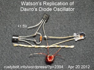
I received a Google Alert and watched Jonny Davro’s Diode Oscillator running from a AA cell and putting out light when connected to, among other coils, a Slinky spring.  I thought that I should have a go at this odd circuit.

I assembled it as he showed in the schematic.  I used the same BC560C for the NPN and a 2N3906 for the PNP; both were new, fresh out of the package.  The diode was a real 4148 or 1N4148.  The LED was a white 5mm, right out of the package.  The coil was a 1/4 inch (6mm) core bifilar wound with 8 turns of 30 AWG, and measured 200 microhenrys per winding.  I tried the single winding and also both windings connected in series.  I also tried a 2N4403 for the PNP transistor.

In all cases, when I connected and disconnected the power supply lead, I saw a feeble flash from the LED, but other than that, nothing.  The current when connected was about 20 milliamps for the 2N3906 and 50 mA for the 2N4403.  I varied the voltage above and below the 1.5V and the current changed as expected, but nothing from the LED.  In the picture I show the LED connected across the coil, but I tried it both ways with the same results.

I suspect that the reason Davro’s circuit oscillates is because he uses a proto board and long clip leads and the stray capacitance of the board and wiring causes the circuit to oscillate.  In my case, there is almost no stray capacitance, so it will not oscillate.  This is just another one of those experiments where results are influenced by outside factors both unintended and unaccounted for.  There’s a lesson to be learned here, I think.

Back to experimenting…

default

2012-04-18 Solid State Relays – Information

on April 18th, 2012 by - Comments Off on 2012-04-18 Solid State Relays – Information

I was looking at This model train web page about using solid state relays.  He gives a few examples of what he calls “home made” solid state relays – I would call them discrete SSRs because they are made from separate components.  There are a few things that I would like to add.

He pointed out that there are advantages and disadvantages to using SSRs.  One thing he forgot to mention is that SSRs are clickless, you won’t hear any clicks or ticks when the ‘contacts’ close. One disadvantage is that they are generally only a single set of ‘contacts’.  If you want to switch multiple ‘contacts’ you have to add more SSRs (but see note at end).

He did say that they are much faster than a mechanical relay, but the speed may be limited by the speed of the optoisolator, which may not be as fast as the transistors used.  Another point is that the optoisolator does not have to be one you’ve purchased.  You can also make your own using a CdS photocell and LED, or two LEDs, with one LED being used as a sensor.  The LED will act as a very small solar cell and generate a small voltage at a small current that can be amplified by a transistor or two.  You can put two LEDs facing each other in a piece of black heat shrink tubing to hold them in place.  You may need to put black sealant on the ends to keep external light out.

One thing that I don’t agree with is he uses the 2N3904 or 2N3906 for currents up to 200 milliamps.  When the current gets to more than 100 milliamps, the 2N3904 or 2N3906 has been pushed to its limit and should be replaced by a transistor that can handle the load without strain.  Choices might be the PN2222A (NPN), PN2907A (PNP), 2N4401 (NPN), 2N4403 (PNP), BC337 (NPN), BC327 (PNP).  These transistors should handle a few hundred milliamps; for currents up to 1 amp the BD139 (NPN) or BD140 (PNP) could be used.  Remember that these transistors are for low voltages; if switching power line voltages is needed, there are high voltage transistors available.

One has to remember that an electromechanical device connected to the SSR, such as a solenoid or motor, might generate a high back EMF or inductive kick.  So it is important that the SSR have the protective diode across its output.  Also the SSR is much faster than a regular relay, so they are more sensitive to external transient interference and it may be necessary to add filtering to prevent interference.

He does not mention anything about using a SSR with AC.  The SSR can be connected to the plus and minus leads of a full wave bridge rectifier, and the AC connected to the AC leads.  The bridge rectifier will drop a volt and a half, due to the forward voltage drops of the diodes, so this has to be taken into account.  If the AC is low voltage, a bridge using Schottky diodes will reduce the voltage drop to half that of a regular bridge.

A lot of equipment now use MOSFETs to switch high current and/or high voltages.  These can be used as SSRs.  But at high power, it is probably better to buy a commercially made SSR to minimize the amount of design decisions and possible failures associated with wrong design decisions.  Also, there may be SSRs made to be used with AC.  These may use a TRIAC that is optically isolated from its control leads.

Note: generally, a common reason for using an electromechanical relay or SSR is for isolating the power circuit from the controller circuit.  The relay can switch much higher currents and voltages than the controller itself could handle.  But relays, especially power control relays, often take quite a bit of power to operate, and once they are energized, they continue to take power.  SSRs can switch high power with less wasted power than regular relays, but there are relays that take no power after they have been energized.  The latching relay may use a ratchet, magnets or other mechanical means to hold the contacts in one position or the other, so there is no contact spring that has to be overcome.  Once energized, the energizing power can be removed and it will stay in whatever position it is in.


default

2012-04-16 Stiffler’s Joule Thief

on April 16th, 2012 by - Comments Off on 2012-04-16 Stiffler’s Joule Thief

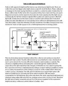
I downloaded Stiffler’s SEC (Spatial Energy Coherence) .PDF and I found this schematic on P.47.  It’s supposed to be for testing how bright LEDs are with a very short pulse.  I found the circuit to be designed for danger; the same high voltage that appears across the primary (collector connected) winding also appears across the feedback winding.  And this is connected through the 1k resistor directly to the base of the transistor.  When there is a positive 43 volts on the primary winding, there is a corresponding negative 43 volts on the feedback winding – the winding ratios are 1 : 1.  The feedback winding is connected to the base without any form of protection against excessive voltage.  We know from the datasheets of many transistors that the emitter to base junction is typically rated at a maximum of 5 or 6 volts reverse breakdown voltage, and if this is exceeded, the junction will break down and permanent damage to the transistor will occur.  So why does he do this to his transistor?  I don’t know.  But it should not be done.

Instead, he should put a white or blue LED from base to emitter, with the cathode or flat spot towards the base.  When the base goes negative greater than 3.3V, the LED conducts and the voltage never rises to greater than 3 or 4 volts negative.

Human eye  I don’t agree with Stiffler’s assertion that “The human eye detects peak light levels.”  The different wavelengths do different things when they enter the eye.  I should say that different wavelengths affect different chemicals, but that may be too simple.  In any case, I’m no expert on it and I think it should be left to an expert to say how the human eye responds to light.

He then uses the term “full brightness.”  Well, what is full brightness?  He doesn’t define it as being any measured value.  And we all know how the human eye tricks us by opening the eye’s iris when the ambient light is dim and closing the iris when the ambient light is bright.  This means that the eye is not capable of making a judgment of how bright full brightness is.

Instead he should go with a definition that is repeatable and measurable.  Such as: The LED is at full brightness when there is 20 milliamps DC flowing through it (for a standard 5mm LED), or if the current is pulsed, then the current that is needed to equal the same brightness as 20 milliamps DC.  For other size LEDs, instead of 20 milliamps, the current it should be set to is its maximum current.

I disabled comments due to comment spam.  Please send email to my yahoo email address acmefixer.

default

2012-04-15 Air Core Joule Thief Without Toroid Core

There’s no law that says that you have to have a ferrite toroid or any core material.  Air core works, but the coil has to have many more turns, which makes it bigger and bulkier.  But if the space is available, there’s nothing wrong with using a reasonably thick wire for the coils to keep the resistance low.  I’ve made quite a few JTs with air core coils, all successfully lighting the LED.

To make a coil, take 16 feet or 5 meters of twisted pair telephone wire and wind it onto an AA cell, then remove the cell and tie the wires into a donut with wire ties, electrical tape or some short lengths of the same wire.  It’s a good idea if the wire is twisted with the insulation on, so it does not make a shorted turn.  You can also use cat5 cable, but it’s twisted much tighter and much harder to untwist.  The white wire of one end connects to the colored wire of the other end, and both are connected to the positive of the AA cell.  Of the remaining two wires, one goes to the collector, the other goes to one end of the 1000 ohm resistor.

Video  This guy seems to have the right idea.  Two hanks of insulated wire, each 10 meters or 39 feet long, tied together for the coil, and it puts out a reasonably bright light.

default

2012-04-14 8V to 12V DC to DC Converter

on April 14th, 2012 by - Comments Off on 2012-04-14 8V to 12V DC to DC Converter
Andrew asked a question about a DC-DC converter:

I need your advise on the following challenge I have an 8 volt 0.3amp solar panel which I would like to use to charge a small lead acid battery 12 volt no more than 10 AH.

Could you suggest a simple JT circuit that could be used to get this done.

Many thanks

Andrew

Well, I’ve been experimenting with many DC-DC converters, including my latest, a high current Joule Thief. I was successful at getting 1 volt at 2.5 amps from my power supply boosted up to 6.6 volts, but the circuit must use very a low resistance MOSFET to ‘do the heavy lifting’.   And I’m still not sure if the circuit will be easy to replicate for the average experimenter.

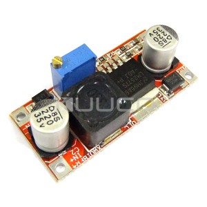
I found a source for a DC-DC converter (step down, or higher to lower voltage) on eBay, for under 2 dollars apiece.  There are other sellers such as this one that sell boost or step up types to convert lower to higher voltage.  The shipping is free, so for a few dollars I can get a DC-DC converter that is 90 percent efficient and is already on a circuit board, so it is very difficult for me to justify building my own – the economics are just too compelling.

All I have to do is mount the circuit board in a small project box along with some jacks or terminal strips and a switch, and maybe a LED to tell when it’s on.  I may also add some filter chokes and/or capacitors and/or ferrite EMI suppressor sleeves to prevent the switching frequencies from getting out and interfering with other stuff.

It looks like this one would serve Andrew’s purposes nicely with an efficiency of 90 percent.  The cost is $5.50 U.S. or about 3 and a half Pounds in the U.K.  They also sell similar ones that are current limited, to drive LEDs.  This may work for charging a SLA battery, however since a solar cell is inherently current limited, the converter itself may not need to have current limiting.
Update Apr 17  I received a reply from Andrew saying that these were too expensive.  I find it hard to believe that he could make one for cheaper (see note at end), but he asked if this one (Youtube video) would do the job.  I think it would but with some changes to protect it and prevent damage.

First off, notice hoe brightly the neon lamp lights up when he connects the circuit up.  This neon lamp is connected from the collector to the emitter of the 2N3055.  A 2N3055 is rated for a maximum collector voltage of 60 volts, and a neon lamp takes about 90 volts to light up.  This is half again as much as the maximum for the 2N3055, and it is absolutely foolish to subject the transistor to such as high voltage.  It will most likely be damaged.

People may think, how can he say that when we can see that it’s working.  Well, they haven’t taken into consideration what is happening in the circuit.  The typical Joule Thief coil is wound with the same number of turns on the primary and the feedback windings.  Therefore if the primary has 90 volts on it, the feedback winding should also have 90 volts on it, but of the opposite polarity.  So when the transistor shuts off, the high emitter to base voltage causes the emitter to base junction to break down, and this damages the transistor by permanently reducing its current gain.

The solution is simple: reduce the number of turns on the feedback winding so that the voltage is much less than the primary winding.  The feedback winding should have no more than 5 or 6 volts negative voltage on the base.

Another simple solution that may be easier than rewinding the coil is to put some form of protection on the base to prevent the voltage from going more than 5 volts negative on the base.  This can be a 5.1 volt zener diode or a LED.  If the zener diode is used, then it must have a 1N4148 diode connected in series with it, to prevent the zener from shunting the base current away from the base.  If this were a small signal transistor such as a 2N4401, the LED would be a good choice.  But the 2N3055 is a power transistor, and the base current will be much higher than for a small transistor, so if the LED is used, it should be a high current LED, or else put several regular LEDs in parallel.

Also, I would eliminate the neon lamp, and replace it with a zener diode.  However, the zener must be able to dissipate the power coming out of the Joule Thief.  This could be a few watts in this case.  So I would use three 1 watt, 6 volt zener diodes in series, across the JT output to the battery leads.  If the battery leads were accidently reversed (stuff happens, and never underestimate the human tendency to do stupid things) then the zeners could be damaged, so it would be necessary to put a 1N4003 rectifier in series with the zeners.

The video showed the diode on the output as a 1N4007, which is a slow recovery diode made for power line frequencies.  At Joule Thief frequencies, it has poor performance because of its slow recovery time.  Instead, a UF4007 fast recovery rectifier should be used.

More about this circuit later.  The guy who made the video, dodoshlodo, made it difficult to get a good look at the schematic, what with his slewing the camera around and putting his hand in the way, so  I’ll try to see more of this excessively long 10 minute video when I have more time.

Note: As I said, I find it hard to believe that he can make a charger for less than what these converters cost ($5.50 U.S. or 3 and a half Pounds in U.K.).  Further more, the typical Joule Thief efficiency is 40 to 70 percent (in this case most likely towards the bottom of that range).  If the DC-DC converter I suggested is used, the efficiency would be 90 percent, and the charging time would be dramatically reduced,  probably to half as long.  This alone more than justifies the difference in cost, if any.

I thought about it, and then it occurred to me that perhaps Andrew is not just making these for a hobby; perhaps he is making them for his business, which would justify counting the pennies.  Perhaps I was duped into helping someone design a circuit for his business.  I give this help to others for use as a hobby, not for a business.  Consequently, I think I may not be offering Andrew further help in  the future.

© RustyBolt.Info/wordpress
CyberChimps