default

2012-08-29 Joule Thief With Timer

I’ve built an automatic shutoff timer into a regular flashlight, and into my Commercial Killer.  Putting a timer into a JT has a very practical use: it saves the battery.  I’m not sure why someone else hasn’t tried to do it, maybe just never occurred to them.  I thought about putting one into a JT with the single 1.5V cell, but since the ones I’ve built use a Darlington pair, and I thought at first that it wouldn’t work at 1.5V.  I went over the voltages and came to the conclusion that the Darlington pair was not a problem (but see my later comments).
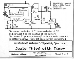
The circuit works just fine when the supply voltage is 3 or 4.5 volts.  The capacitor takes a couple minutes to discharge and the light stays bright.  But the JT’s single cell has only 1.5V, which is too low.  To remedy that, I decided that I would rectify the JT’s output to the LED, so I can get 3 or more volts to the 47 uF timing capacitor.  That’s why I added the two diodes, D1 and D2.  D1 lets enough voltage through to the capacitor to start the circuit, then the JT adds 3 or so volts through D2 to the capacitor.

Old Joule Thiefs don’t die, they just fade away – The LED doesn’t go out abruptly; it fades away over about a minute.  The 47 uF gives about a minute and a half of bright LED, then it starts to dim.  This gives you a warning that you have to press the pushbutton again to restart the timer.  This cap can be changed or one or more switches can be added to allow the user to select the time.  100 uF should give 2 or 3 minutes.  But some larger electrolytic capacitors have some leakage that can discharge the voltage even without anything connected, so don’t expect large capacitors to give an accurate timeout.

The circuit works fine at 1.5V, which is equivalent to a fresh battery.  But there is only a little more than 0.1 volt across R4, and Q3’s base current seems to not be enough, because the voltage drop across Q3 is about 1/4 volt – it should be lower.  The value for R4 may have to be reduced, but even at a lower value, if the battery discharges below 1.4V, the circuit may have trouble.  I turned down the supply, and found that at 1.35V, the circuit works poorly and at 1.25V the LED is very dim.  This is caused by the Q1 and Q2 Darlington pair, which requires a minimum of 0.6V at the collector.

My solution is to disconnect the collector of Q1 from the collector of Q2 and connect the Q1 collector directly to the battery positive.  The voltage across R4 increased to 0.75V, and that allowed me to increase R4 to 1k.  With this single change, the JT puts out full brightness with the battery voltage at 1.25V, and works to less than 1V.  It is much more tolerant of a discharged battery than it was before.  Now it will work okay with a Ni-MH rechargeable cell.  Also the LED stays brighter for a longer percentage of the total time it’s on, and it goes out quicker.

Change for the better – But then I wasn’t thinking when I drew the schematic.  My Blue Blinky and others used a circuit to control the JT, but they did not switch the whole current to the JT, only the bias current to the base.  So I removed the primary winding of the coil from Q3, and connected the winding directly to the battery positive.  Now only the bias to the feedback winding and then to the base is switched by the timer.   The current through Q3 is dramatically reduced.  I haven’t done it yet, but I can increase the value of R4 to a much higher value. something like 3.3k or more.  I took a 3.9k out of the parts box and put it in, and it works okay; the LED lights brightly.

But an interesting phenomenon has now occurred.  The currents in Q1, Q2 and Q3 have been reduced a lot, and the time has been extended.  Before the LED was starting to get dim at  2 minutes and then no light at 2 and a half minutes.  Now it hasn’t started to get dim at 3 minutes, and about 4 minutes it has dimmed noticeably, but not gone out.  After another minute, the LED was still very dimly lit, but the supply current was very low.  When I brought my finger next to, but not touching the Q1 and Q2, the LED lit up brightly.  The currents in the circuit are so low and the impedances so high that it is now a detector of any hum or interference.  I turned off the soldering iron and the LED went almost out.  When I have my hand near it and I shuffle my feet on the carpet, the LED blinks.  An electrostatic field detector?  Weird!
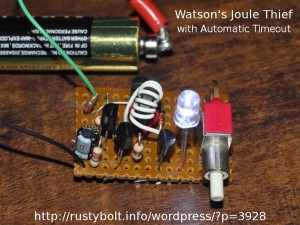
Update  Sept 1 – I assembled a second JT w/Timer on a piece of perfboard – the original was just tack soldered together.  I used identical components except for Q3, which I changed to a 2N3906 since it now carries so little current (but the BC327, 2N4403, PN2907A or any other PNP will work okay).  I built it to validate the design.  It works as well as the original, and fits (minus the oversize pushbutton) on a board about the size of a postage stamp  That switch was salvaged from the motherboard of a telephone PBX.  When I had to push that reset switch, up to 200 phones would suddenly go dead(!)  And they would stay dead for the next 5 or 10 minutes while it was rebooting.

Back to experimenting…

default

2012-08-28 Headphone Amplifier Hub-Bub

I unpacked my ol’ headphone amplifier and tried to find the wall wart AC adapter for it.  The jack is labeled 12VDC, center negative, so I looked through some boxes for the adapter that matched up.  I found one and plugged it in, turned on the amp, and heard Hum-Bub, Hum-Bub, Hum-Bub…  The amp was motorboating on both channels, with a lot of hum.  Hearing that both channels were the same, I knew that the problem was common to both channels.  I’m thinking that the problem is that it’s the wrong AC adapter.  The amp needs 12V at a couple hundred mA, so I connect it up to an HP variable regulated power supply.  The amp is dead silent, no hum, no motorboating, and works great.  I now know that the problem is in the power coming from the AC adapter.

I decided to change  the AC adapter.  The adapter I changed to puts out 16VDC no load, and 14V when on the amp.  That’s a little high, but ok for the amp.  I connected it up and still heard Hum-Bub, Hum-Bub, Hum-Bub…  So I clipped a 2200 uF capacitor across the DC input, and the hum was reduced dramatically, but the motorboating was still there, just slower.  I added a second 2200 uF, and I got less hum and slower motorboating, but it wasn’t eliminated.  I’m thinking that I’m headed in the right direction, but just not enough.  So I decide to put a 10 ohm resistor in series with the +DC lead.  That helps some more, but it’s still doing Hum-Bub, Hum-Bub, Hum-Bub… just a lot weaker and slower.  I’m just not making enough progress.

I figured an easy solution would be to use a 7812 three terminal voltage regulator IC.  The problem is that it needs a few volts from input to output to keep working correctly, and the adapter is putting out only 14 volts under load.  There is nothing to spare, and when the AC power line drops lower, the  IC will drop out of regulation.   I could use a LM317 adjustable regulator IC, and set the output for 11 volts.  But the headphone amp was really supposed to have 12VDC.  Then after a little thought, I came up with the idea of using a capacitive multiplier.

Capacitive Multiplier – This circuit consists of one transistor (typically a power transistor since it handles the current for the whole circuit), two resistors and an electrolytic capacitor, typically hundreds or a thousand micofarads – I chose 1000 uF.  The two resistors are typically 10 to 1 ratio – I chose 3300 and 330 ohms.  The 330 is connected from collector to base, and the 3300 is connected from base to ground.  This biases the base at a few volts below the collector.  This transistor is a common collector or an emitter follower, where the emitter follows the voltage on the base.  The capacitor is in parallel across the 3300 ohm resistor.  The filtered power is taken from the emitter.  The 330 ohm and capacitor form a low pass filter, drastically reducing the ripple from the rectified and already filtered DC.  A small amount of current is used by the base, and the much higher current from the collector passes through to the emitter, which follows the very filtered and very low ripple voltage at the base.  It’s called a capacitive multiplier because the thousand microfarad capacitor looks like it is multiplied by the current gain of the transistor, which can be fifty or a hundred times or more.  The 1000 uF capacitor can do the same filtering as a 100 thousand microfarad capacitor.  The penalty is that the transistor drops a few volts, so the output at the emitter is a few volts lower.  In my case, this three or so volts drop makes the output 12.3 volts, which is just about perfect for the amp. The other advantage is that if the AC adapter’s output drops, the voltage divider keeps the voltage drop the same, and the output drops some.  The amplifier is class A and the current is fairly steady so a small change in voltage will not matter.  If I wanted to maintain a constant output voltage, I could have replaced the 3300 resistor with a 12V zener diode, and the output would be kept at about 11.4 volts.  But the amp doesn’t need that much regulation.

Get it together – I assembled the above parts inside of the case, and mounted the transistor to one of the existing screws.  The 1000 uF capacitor dropped the hum to almost inaudible, and the motorboating stopped.  But the slight amount  of hum that I could still hear was eliminated by putting a 470 uF capacitor across the 1000 uF, for a total of 1470 uF.    The amplifier works great, and the circuit will now work on just about any 12V unregulated (16V no load) wall wart that I want to use.  I could also use a 12.6VAC, 1/2 amp power transformer along with a full wave rectifier and filter capacitor, but the AC adapters are easily obtained from surplus places such as MPJA.com, All Electronics, Goldmine Electronics, etc.

Back to experimenting, and now I can listen to my music!

default

2012-08-27 High Voltage Joule Thief Schematic

High Voltage Joule Thief Schematic – In this Youtube video, we see the circuit connected to and lighting a neon lamp.  I corresponded with the author and he gave me permission to post the schematic to my blog. Here is the link (it’s a .PDF).  High Voltage Joule Thief

The author sent me some closeup pics of the device.  If I get permission, I’ll post one here.


default

2012-08-23 Watson’s Supercharged Joule Thief Flasher Photo

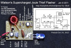
I think this picture and schematic was posted to my watsonseblog. but it didn’t get posted to this rustybolt.info/wordpress/ blog.  It’s a picture of my SJT Flasher with the parts labeled, and a schematic of same (click on the picture more than once to enlarge).

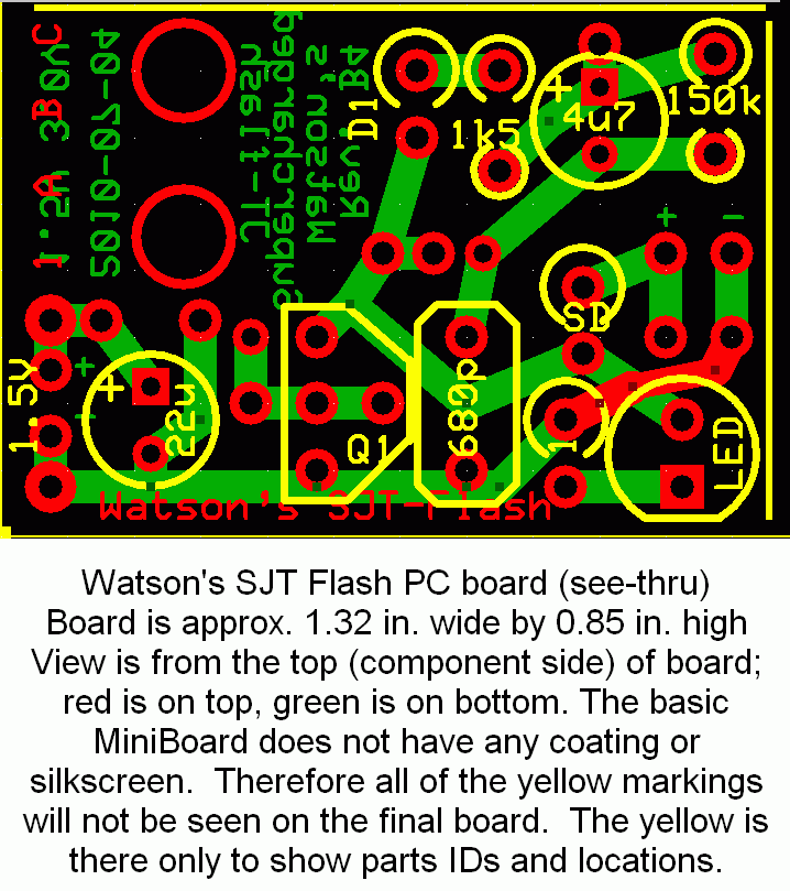
I looked in my folders and found another picture of the PC board.  I don’t have a PC running Windoze at home and I can’t access the PC board files on disk because the program that accesses them only runs only under Windoze.   This file lets anyone look at all three layers of the PC board at the same time.  When I sent the file in to have the PC boards made, the ExpressPCB company did not offer the “Miniboards” with a silkscreen layer (yellow in the picture).  They do offer it now, for an additional cost.  Paul asked me about this board, and at this time this is as much as I can find.  Until I get a Windows PC or the company offers a software version that runs under Linux, I am not able to update the circuit board.SJT-Flash-2(PCB)

The LED turns on when power is applied, and the 4u7 begins to charge up.  When it has charged up, the SJT shuts off and waits for the 150k to discharge the 4u7.  Then the cycle repeats.  Quantsuff did some experimenting with it on his web page, www.quantsuff.com.

The two smaller holes, one above the 680p and the other next to the collector are the feedback winding leads.  The primary leads are near the 22u “+” and collector.  The filtered DC output is at the two holes below the + and – holes.  Or you can move the LED to these holes.

A 1 ohm resistor or a jumper goes in the holes labeled ‘1’.  This is for measuring the LED current.  For example, 20 millivolts equals 20 milliamps.

The SD is a (Schottky) diode to rectify the output.  The filter capacitor goes in the holes with + and – to the right of the SD.

What you can add to this board is a CdS photocell across (or in place of) the 680p capacitor.  The 4u7 should be replaced with a 47 pF or 100 pF capacitor, and the 150k by a 100k pot or whatever resistor you choose to determine the brightness and current.

You can remove the SJT and make it into a regular JT.  Just remove the 680p, jumper D1 and the 4u7, and change the 1k5 to whatever resistor you choose to determine the brightness and current.

default

2012-08-21 Directional Microphone

I came across and article in an old electronics magazine on how to make a directional microphone with a cardboard horn.  I decided to copy the horn part.

The horn consists of four triangle shaped pieced of cardboard cut from boxes.  Each of the four pieces is 1 inch (25.4mm) at the small end, 12 inches (300mm) at the large end, and 24 inches (600mm) long.  The line from the small to large end has a 1/2 inch (12.7 mm) ‘sag’ at the 12 inch point, and 1/4 inch (6.3mm) ‘sag’ at the 6 and 18 inch points.

I assembled it with short lengths of clear adhesive tape, then covered all the seams with the heavier 2 inch wide box tape.  The curved sides help stiffen it, but it still wasn’t very stiff.  I hot glued most of the seams on the inside, and that helped stiffen it a lot.

I still have to mount the microphone and connect it to a microphone preamp.

default

2012-08-20 Bedini Motor

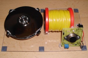
Peter sent me a picture of his Bedini motor, with its colorful coil (see the attached picture).  He says it draws 30 milliamps at 9V when running at maximum speed.  There seems to be a large following of this Bedini SSG device, especially among the Free Energy advocates.  It is called Bedini SSG, for Simplified School Girl.  I’ve been following the Bedini weenies for a few years, and I joined the Yahoo group Bedini Monopole 3, which is now in the process of getting a forum up and running.  It’s an interesting circuit, much like a Joule Thief, but it will not run without the magnet wheel.   It runs off a 12V battery, typically a SLA, known as the running battery. The collector voltage is rectified and fed to a second battery, which is known as the charging battery.  But I’m not sure what the device is supposed to accomplish, because it doesn’t generate free energy.

I tried building one using the innards of a CD drive.  The Bedini instructions recommend that the builder cut up welding rod into short lengths and insert them into the core of the coil.  Instead, I used steel wire, which was thinner.  They recommend using two windings, one with 23 AWG and one with 26 AWG wire.  Instead, I used three windings of 26 AWG, with two connected in parallel.  They recommend using a 2N3055 power transistor, which has a collector voltage rating of 60 volts maximum.  They recommend putting a neon lamp across the emitter and collector, as an overvoltage protection.  This seems like a bad idea to me, because the 2N3055 is rated for 60V max, but the neon lamp lights up at 90V.  They recommend using a LED from base to collector to prevent reverse breakdown.

My wheel was plastic because they tell the builder to not use a steel bicycle wheel.  They tell us to not use neodymium magnets, but I used them because I did not have any other small magnets.  The magnets must be a certain polarity, north or south facing out, I forget which.

I lashed up the circuit and powered it up.  It did not work, and I did not pursue it any further, I just figured one of the recommendations I deviated from caused the problem.  I do not want to pursue it again, because I don’t see what the point is.  Also, I think the circuit needs to be redesigned for more protection.  Many of the builders complained that they have burned out the 2N3055 and had to replace it.

By the way,  Bedini patented the circuit, but they have said that he gave permission to build his circuit.  They sell kits, and a lot of builders buy them and assemble them.  Many of their pictures are posted to the group.

Thank you Peter.  Someday I may dig out the parts and take up the soldering iron, and try to make a successful SSG.  But not at this time.

default

2012-08-19 Repeal Ban on 100W Incandescent Bulbs?

Something is seriously wrong with legislators who take such a radical view of the laws.  This article tells us that some members of congress are trying to repeal a law that is supposed to reduce the use of electricity and save consumers a lot of money.  I think that this is another indication that the government is dysfunctional.  And for what?  They tell us that even if the ban on 100W bulbs is enacted, the manufacturers have already stopped producing them.  Sometimes I wonder what these legislators have on their minds.

default

Protected: 2012-08-18 Grijalva Park

on August 18th, 2012 by - Enter your password to view comments.

This content is password-protected. To view it, please enter the password below.

default

2012-08-17 Joule Thief Plus 22 nF Capacitor

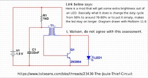
I received a Google Alert with a link to a forum in which the poster declared that adding a 22 nF capacitor to the conventional JT will increase its brightness.  I’ve read this claim previously and I tried the circuit (see attached pic) and I found that the LED went from  bright without the capacitor to dim when I added the capacitor.  But just to triple-check, or more like quintuple- or sextuple-check, I again within the last hour soldered a Joule Thief together, and then connected the 22 nF capacitor.  Again, when the capacitor was not connected, the LED was bright.  But when I added the capacitor, the LED again went dim.  The difference was dramatic: it wasn’t just a little bit dimmer, it was much, much dimmer.  The LED was useless for illumination with the capacitor connected.

I’m not sure where these people get this spurious information.  The poster claimed, well, you can read it in the link or in the schematic.  I don’t think anyone who has made this claim has ever put the circuit together.  If they had done so, they would have seen how really bad this circuit performs.  The poster said that he had drawn the circuit in Multisim.  If he simulated the circuit and got the results he made in his claim, then I would say that his software is unable to simulate the actual circuit, and it’s time to get rid of it and instead do it in the Real World.

One thing is for certain.  If he or she replaces the 2N3904 with a 2N4401, the LED will get brighter: the LED current will go from under 10 mA to closer to 20 mA.

default

2012-08-16 Steampunk Style LED Lamp, etc.

My now retired co-worker gave me a present with some bars of Blissed Out Soap, which gives a website on the wrapper.  I have been fascinated by homemade soap since I was a child, and watched our next door neighbor make soap out of bacon grease and lye (sodium hydroxide).  This soap is very fragrant, smells great, but I haven’t had a chance to try it yet – all in due time.  While I was there, I typed in LED into the search box at the top and came up with some very interesting stuff under LED lamps.  One, a retro style lamp, caught my eye.  I’m not sure if it would be called Steampunk, a name which seems to be applied to anything that is new but eclectic and antique looking.  I really like the look of this lamp, but one thing that really concerns me: how long the LEDs will last.  I have done lifetime tests on LEDs, and these small LEDs often last less than a thousand hours.  Someone gave me an inexpensive LED tamle lamp with a row of a dozen 5mm white LEDs.  I had it running for much less than a year and the LEDs all became dim, and it was useless as a light.  It’s not such a big deal when the lamp costs ten or so dollars, but when the lamp costs hundreds of dollars, this becomes a serious issue.  I could open up the table lamp and replace the LEDs; one cannot open up the glass envelope of this expensive lamp and replace the LEDs easily.

Another one that interested me was a submersible LED light.  It’s a really good idea, because LED lights are often used where the weather is wet, or in high humidity environments.  They’re cheap too; ten for ten dollars U.S.

Looking through the LED lights, I saw that many used a CR2032 lithium coin cell.  One reason they use these is that the 3V cell can power a LED by itself, with no resistors or other circuitry.  The internal resistance of the cell is enough to limit the LED current.  Those keychain LED fobs that we see in the checkout line do the same thing: they connect the cell directly to the LED.  One product said that the cell lasts for 48 hours.  After looking at other products, observation is that there is considerable room for improvement in the technology used in these products.  First off, with the technology used in a Joule Thief, the designer could be freed from using multiple coin or button cells.  And with my Supercharged Joule Thief circuit, the battery life could be extended considerably.

But for seriously long battery life, and given the limitation that the LED must flash, my Blue Blinky circuit would allow the LED to flash for more than a year on a single AA cell.  A Christmas decoration with up to a dozen LEDs would be able to run on a single cell for a month or more, which is long enough to get it through the Xmas season.  The LED color does not have to be limited to blue; other colors could be used.  And with surface mount parts, the board with a half dozen or more individual circuits would fit in the space of a AA cell.  Also, there is a flashing Red LED circuit (see my blog) that does not use an inductor, instead it uses a switched capacitor, AKA charge pump.  This would save the expense of the toroid core and winding the JT coil.

© RustyBolt.Info/wordpress
CyberChimps