default

2012-09-09 Joule Thief It’s Not

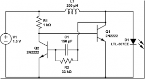
I received a Google alert for this website, which is clearly labeled as Joule Thief.  As can be seen, the circuit shows two transistors. a single winding coil and a few other parts, which are indicative of a voltage boost circuit but definitely not a conventional Joule Thief.

Some people accuse us of being pedants.  Look, all horses are four-legged animals.  What would you say if I called that four-legged animal laying on the couch and purring, a horse?  What you say if I called that small four-legged animal wagging its tail a horse?  Not all voltage boost circuits are joule Thiefs, and unless someone challenges those who make this mistake, those mistakes will continue to happen.

default

2012-09-08 Light Beam Communications System

Long ago I built a light beam communication system.  It was sophisticated in that it Frequency Modulated the carrier so that it was relatively immune to interference from light sources.  The light emitters were small indicator grade LEDs.  Even so, I was able to get it to work at a thousand feet (305M) with the help of optical concentrators (lenses).  Since then I have been buying much more powerful LEDs such as the 1Watt Luxeon Star.  So I decided to experiment with a more powerful emitter, the red 1W Luxeon Star.

I first connected the LED to a power supply with a 10 ohm current limiting resistor which also served as a current measuring point. I adjusted the PS until I measured 2 volts across the 10 ohm, which meant that the LED 200 mA was passing through the LED.  It didn’t get excessively warm after a few minutes, so I figured I could go somewhat higher, considering that the white 1W Luxeon LEDs can handle 350 mA; the red LEDs are lower voltage and should be able to handle more current, probably 400 mA.

Under cover of darkness, I used the camera lens at first, then a lens from a magnifying glass.  I could focus the LED onto a fence about fifty feet away.  Then I tried focusing on a tall palm tree more than a hundred feet, but I couldn’t see it clearly, probably because I was holding the lens with my hand.  I needed to mount it to something.  But before that I needed to fabricate a modulator and detector.

For the detector I used a solar cell connected to a 150 ohm earphone from a telephone handset.  The Amplitude Modulator I came up with was simple: just build a high current common emitter amplifier with a Darlington transistor pair, and put the LED in series with the collector. This gave me control of the current through the LED and it would bias the LED so that it was emitting light all the time.

I used a pocket radio for the audio source so I could just tune it in to a local station that would broadcast mostly music.  I plugged the modulator into the headphone jack. It was a little ragged at first, so I put a 100 ohm resistor across the output to simulate a speaker load.  With an adjustment of the volume control, the sound from the earphone sounded pretty good.

Now I need to work on the lenses.  I had some Fresnel reading lenses but they’re packed in some box, I don’t know which or where.  These are about the size of a page of paper, big enough to cover the whole page of a book.  But they’re very flexible, so I may have to mount them in some kind of frame.  So for now, I’m using a 3 inch magnifying glass to focus the LED.

default

2012-09-07 Lighting Control – Some Important Questions, Considerations

I put a timer on one fluorescent light and started thinking about what I had talked about in one of my earlier watsonseblogs.  This topic is very important, but is seldom considered, and lack of understanding and consideration causes a lot of waste and money.  First I’ll have to discuss the way it used to be before CFLs replaced incandescent lamps.

Back when timers were used on 60 to 100 watt incandescent bulbs, the power that the timer used was a small fraction of the light bulb power.  But the CFLs use 1/5 as much power as the old, inefficient incandescents, and the power that the timer uses is now a much greater percentage of the CFL power.

I will use the term Wh for the amount of Watt-hours that a device uses.  If a 100 watt bulb is lit for 10 hours, it will dissipate 1000 Wh, or 1 kWh, which is 1 kilowatt-hour.  This topic applies to the electrical control of any device, not just lighting.

One has to remember that the timer is on 24 / 7 and uses this small amount of Wh all the time.  A mechanical timer may use 2 or 3 watts (you can feel it’s warm).  If you are going to use this timer to control a small wattage lamp, then the timer may use, on the average, as much or more power as the lamp over time. If not more, then it may use a sizable fraction of the lamp’s Wh.  This also applies to the motion sensors and daylight sensors that are often used in lighting fixtures.

What this means is that the timer is actually adding to your electric bill, not saving money.  You will be better off if you remove the timer and plug the low power light in and control it manually. Let’s try an example.  We have a 3 watt light controlled by a timer that uses 3 watts.  We want  the light to be on 6 hours a day and off for 18 hours.  We want to save 18 times 3 or 54 Wh (watt- hours) a day.  The timer uses 3 watts times 24 hours or 72 Wh.  So in actuality we lose 18 Wh per day.  We would be better off leaving the light plugged in 24/7 instead.

This same situation occurs when a light is controlled by a daylight sensor.  I bought a nightlight that has a single LED and a daylight sensor.  The sensor uses a 555 timer chip, which most likely takes as much or more power as the LED.  It is wasting half its power or more during a 24 hour period.

Let’s think about the CFL.  A common CFL lamp uses 13 to 20 watts, about equal to a 60 to 100 watt incandescent.  The timer uses 3 watts.  The timer is set to turn on the CFL for 6 hours a day.  That is 13 watts times 6 hours or 78 Wh per day.  The savings is 13 watts times 18 hours or 234 Wh.   The timer uses 3 watts times 24 hours or 72 Wh per day.  Subtract 72 from savings of 234 and it ends up actually saving 162 Wh a day.  But if the CFL was being manually controlled, the savings might be equal to or better than 162 Wh.

One other factor we have to consider is the cost of the equipment – for instance a timer might cost $20.00 (US).  If I add up the electricity savings of the timer over a year, it may add up to only a dollar or two.  It may take ten or more years of savings to pay back the cost of the timer.  And in my experience, the timers have a motor that  stops working after a few years, maybe five or so years.  Then it has to be replaced.  in other words, the cost of the timer is never paid back in electricity savings.  This hidden cost is very important, and should be brought to the attention of the consumer by the consumer agencies.

To sum it up – What we have here are a bunch of hidden costs that are literally defeating our attempts to save money and help the environment.

Update Sep 13 – I’ve been thinking about this problem.  I received a LED light from my co-worker; he purchased it from Microcenter for 13 dollars.  The brand name is Inland, it’s a 60 watt replacement, uses 10 watts, and is warm white.  He wants to use them in a motion sensing security light.  I figured that if the motion sensor circuit uses 1 watt and is on 24 hours a day, 7 days a week, the total use per year would be 8760 watt-hours or 8.76 kWh per year.  If the light goes on at night for a total of 1/2 hour, the total use per year would be 1825 watt-hours or 1.825  kWh per year.  Added to the motion sensor usage, that would total 10585 watt-hours or 10.585 kWh per year.  The motion sensor clearly uses most of the energy in this case.  Oops, I forgot; there are two light sockets.  In that case assume only one socket is used, but even with two lights the motion sensor circuit is still the energy hog.

If he were to connect the single light directly up to the AC with no switch, it would run 24/7 and use 87600 watt-hours or 87.6 kWh per year.  If it had a daylight sensor, assuming 12 hours a day average, that would be half as much or 43800 watt-hours or 43.8 kWh a year.


default

2012-09-06 Philips L Prize LED Light

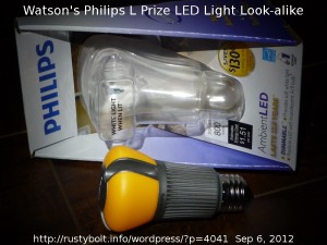
The article in the Oct 2012 Consumer Reports on LED lights mentions the L Prize, so I googled it.  I found out that the DoE awardrd the L Prize to Philips.  The light looked just like the one I bought but on closer examination I found that the one I bought is 12.5 watts whereas the L Prize light is only 10 watts.  Mine was made in China, the L Prize light was made in the U.S.A., Wisconsin to be more precise. The L Prize light costs $50, mine cost half that much at the big box store.  But even at that price, it was still expensive.  One will have to use the light a lot during the next two decades in order to save enough electricity to pay for the extra cost.

That’s the big problem right now: cost.  I can buy a CFL for a dollar at the dollar store, and it’s not much different and does a half decent job.  My friends have said that the cheap CFLs don’t last very long and burn out.  I think the reason why is because many of the CFLs are installed in sockets that point the bulb down, so that the heat from the ‘corkscrew’ rises up into the base and overheats the circuit inside.  Premature failure is the result.  For this kind of socket, the cheap CFLs are a poor choice, instead use a more expensive brand.  Keep your receipt and be prepared to get a refund when it goes bad.

CFLs, fluorescents and LED bulbs have cut my electric bill down a lot.  To cut back on electric usage, I have put a timer on one light, and bought some lights with daylight sensing.  But I have some important unanswered questions, and I’ll go into those in my next blog.

default

2012-09-04 V Booster, NPN-NPN (often mislabeled a Joule Thief)

Quantsuff gave me permission to post his schematic of the two NPN transistor voltage booster, often mislabeled a Joule Thief.  This uses an NPN transistor to drive the output transistor, which is also NPN.  The commonest two transistor V booster uses a PNP to drive the NPN output transistor, and for good reason, as I explain below.

I should explain why I know a bit about this circuit.  I first started using the single transistor voltage booster, later known as the Joule Thief, more than ten years ago but due to my inexperience with the very high current demand on the transistor, I didn’t get the performance that I was expecting.  So I changed to the two transistor designs, including this one.  I got better performance from these so I used the two transistor design to build my first batch of single cell LED lights.

Demanding – There are at least two criteria that must be met to get this circuit to put out enough current to the LED.  First off the output transistor Q1 must be able to switch high enough current.  When this transistor is fully on, the collector voltage should be less than 1/4 volt.  Then the resistor R1 supplies the current to cause Q1 to saturate, so this resistor must be low enough to allow that high current.  Remember that the supply voltage is only 1.5V, and the base to emitter voltage is at least 0.6V (probably more like 0.7 or maybe more), so the voltage across R1 is less than 0.9V.  I used a BC337 for Q1 and I used a 470 ohm resistor to get the Q1 base bias current up high enough to cause Q1 to fully saturate.  But my calculations show that it might be 100 ohms or even less.

Once we get Q1 to saturate, we then need to get it turned off.  In order to do this, Q2 must shunt the base current of Q1 to ground.  Q1 must turn fully on and drop its collector voltage to less than 0.6V, which is the base voltage of Q1.  So R2 has to be low enough to cause Q2 to fully turn on and saturate.  Thus, R2 must be less than a certain value depending on the current gain of Q2.  I put a 100k pot there and adjusted it lower and higher.  At the higher settings the collector voltage of Q2 / base voltage of Q1 was too high and the circuit put out less light and drew excessive current.

Some experimenters love to put adjustable resistors AKA pots in there and see what the circuit does.  A good designer will calculate the resistance value assuming minimum supply voltage and minimum gain for the transistors, and then use that value in the circuit.  But there’s not much fun then, is there?  One other point.  The circuit must have enough gain to start oscillating when powered up.  The gain of Q2 must be high enough to get it oscillating.

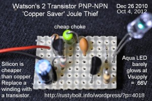
The PNP – NPN version of this circuit (see photo) is different in that when Q2 turns on, its collector current turns on Q1’s base, and therefore the Q1 base current is not determined by the resistance.  Instead it is determined by how hard Q2 is turned on, and that could be tens of milliamps.

Back to experimenting…

default

2012-09-03 Alphanumeric LED Display

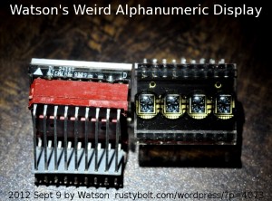
I pulled these Siemens DL 2416 from an old PBX.  They are seated into an 18 pin right angle adapter that reduces the size down to the standard 0.3 inch wide pattern.  I found the datasheet for these online.  Each character of the four character display consists of small segments of red LEDs. There is a decoder on the display, so it’s just a matter of feeding the display characters.  More on this in the datasheet (PDF)DL2416T.

I did a Google search for it and I saw something about this display and Arduino, so check out the search hits to see what’s out there.  Maybe there’s free software out there for it.

Seems that nowadays no one wants to mess with LED displays because they are power hungry compared to the LCD displays.  That’s true, but the LED displays can be used in line powered equipment without being detrimental.  Obviously we can’t compare these to a full color LCD display like we find even in the cheapest cell phones.  But they can display a good set of characters – see the datasheet.  Two of these have a total of 8 characters, but the characters can be scrolled in software, so a whole line can be displayed slowly.

default

2012-09-02 2SC945 Not a Good Choice For a Joule Thief

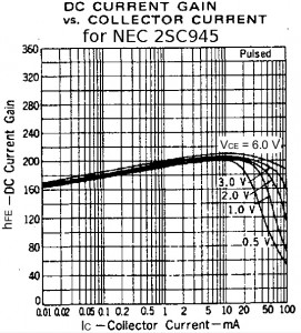
I blogged Anton’s HV JT and noticed that it uses a 2SC945.  I googled for 2SC945 datasheet and found a .PDF of the datasheet from NEC.  It showed that the absolute maximum collector current is 100 mA, which is way too low for a Joule Thief, which needs several hundred mA.  I scrolled down to the page with the graphs and found one that said Current Gain VS Collector Current (see the attached picture).

What we want for our JT is a transistor that has good current gain holdup at high currents and low collector voltage.  At saturation, the collector voltage should be 1/4 volt or less at several hundred milliamps, and the gain should be reasonably close to what it is at much lower currents.

The Graph Doesn’t Lie – Looking at the graph, we see that it doesn’t go more than 100 mA on the right.  That’s not enough for our JT.  We notice that when the collector current is 10 mA, the current gain is about 180 at any collector voltage (Vce).  But when the collector current goes up to 100 mA and the collector voltage goes down to 0.5V, the current gain has suffered greatly – only 50 which is less than 1/3 of its 10 mA value.  And we’re going to want the transistor to have high current gain at 1/4 volt and 2 to 300 mA, which is even more demanding on the transistor.  What the graph implies is that the 2SC945 was made for moderate currents much less than 100 mA, and was never meant to do an adequate job as a Joule Thief transistor.

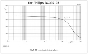
What to do?  Let’s look at the datasheet for the Philips BC337-25.  It shows the maximum collector current is 500 mA. five times that of the 2SC945.  Then we look at the graph of current gain vs. collector current (see attached pic).  The graph shows the beta (current gain) holdup at high currents and low voltage is much better than the 2SC945. In practice the BC337-25 will put out about 20 milliamps to the LED and draw about 80 milliamps from the battery. And it’s mre efficient than the 2N3904 or 2SC945.

default

2012-09-01 Question Of The Month

Question Of The Month:

Every duplex electrical outlet should come with a 5V USB charging port built into the outlet next to the sockets.

[ ] I agree

[ ] I disagree

Well, I’m afraid that someone has already thought of that*.  I was in the Big Box home improvement store this weekend and they’re selling a six outlet adapter that takes the place of the faceplate on the wall.  In addition to the six sockets, there are USB charging ports on the top, just waiting to charge your favorite hand held device.  You just have to furnish the charging cable.

What next?

* I found it on Belkin’s website.  But when I clicked on it, it gave an ‘internal server error’ so maybe later it might work.

default

2012-08-31 OTG USB Adapter

My co-worker asked me to do some soldering for him.  He had a micro USB cable that he wanted to convert to an OTG cable.  I didn’t know what an OTG cable was, but he told me that all I had to do was connect the pin five to ground on the micro USB connector.

i decided that I had to do some research on this, so I googled OTG cable and came up with a Wikipedia article.  It said that normally the micro USB device is a slave; it acts like a storage device, not a computer.  So grounding the pin 5 tells it to act as the host or computer, so you can plug other storage devices or a keyboard or a mouse into it.  That’s pretty cool, you can add a second flash drive, for instance.  Or connect it to a USB hub, and do multiple devices. BTW, OTG means On The Go.

I started working on the cable about quitting time, and managed to get the jacket removed and see some of the wires.  But there were only four wires in the cable, there was no fifth wire.  So I cut away part of the connector itself, until I got to the bare copper shield that covered the whole connector.  I told him that I would try again tomorrow, but he said that  he would try to find it.

I came back the next day and he had cut away all of the plastic around the connector and the wires were bare.  So I soldered the pin 5 to ground and did some repairs to the cable to make it serviceable.  He plugged a mouse into the cable and the cable into his tablet, and it worked.  Cool!  So I said I gotta get me one of those.

I looked on Amazon and eBay, and they wanted anywhere from 7 dollars to more than ten dollars for a single OTG cable.  I figured I could find it cheaper.  I found that Dealextreme.com was selling them for a dollar sixty apiece so I ordered several and the shipping was free.  In a few weeks I’ll have them arrive in the mail.  Maybe I’ll be able to get my cell phone to allow a flash drive to be plugged in.  Then I can download those pictures into the flash drive.  Cool!

Back to experimenting…

default

2012-08-30 Exciter (Mini Tesla Coil)

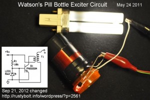
Last year I experimented with the exciter that I saw on a Youtube video.  It’s a simple circuit, and does some eery things, like light up a nearby CFL without  any connection.  The picture shows the schematic and how simple it is to implement.

© RustyBolt.Info/wordpress
CyberChimps