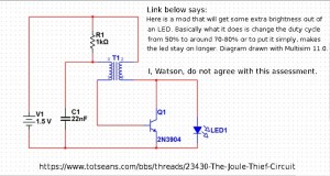
 I received a Google Alert with a link to a forum in which the poster declared that adding a 22 nF capacitor to the conventional JT will increase its brightness. I’ve read this claim previously and I tried the circuit (see attached pic) and I found that the LED went from bright without the capacitor to dim when I added the capacitor. But just to triple-check, or more like quintuple- or sextuple-check, I again within the last hour soldered a Joule Thief together, and then connected the 22 nF capacitor. Again, when the capacitor was not connected, the LED was bright. But when I added the capacitor, the LED again went dim. The difference was dramatic: it wasn’t just a little bit dimmer, it was much, much dimmer. The LED was useless for illumination with the capacitor connected.
I’m not sure where these people get this spurious information. The poster claimed, well, you can read it in the link or in the schematic. I don’t think anyone who has made this claim has ever put the circuit together. If they had done so, they would have seen how really bad this circuit performs. The poster said that he had drawn the circuit in Multisim. If he simulated the circuit and got the results he made in his claim, then I would say that his software is unable to simulate the actual circuit, and it’s time to get rid of it and instead do it in the Real World.
One thing is for certain. If he or she replaces the 2N3904 with a 2N4401, the LED will get brighter: the LED current will go from under 10 mA to closer to 20 mA.
I was looking at this circuit
http://www.discovercircuits.com/PDF-FILES/3vledfs1.pdf
And I was wondering if there was a way to change the normal transistores for FETs, not changing the rest of the circuit, if possible.
Considering a change, what type of FET should I use and what wold be the advantage (less consumption or efficacy)?
If you look at other schematics designed by David Johnson, you will see many that use FETs. But this one doesn’t, and this is why.
The FET is different than a BJT (bipolar junction transistor) in that it requires a comparatively large voltage on its gate, typically 1 volt up to several volts, even more than the 3V supply voltage, which would prevent it from turning on in that case. And the variation in voltage from FET to FET is large, which may make it necessary to select the right FET from many FETs. So even if the FET could be selected to operate below 3 volts, it would still need major changes to the circuit to get the voltage changes that would be needed. And the circuit is already low consumption and very efficient.
Then the FET costs a lot more than a BJT, maybe ten times or more and they’re more difficult to obtain. The two transistors used in the schematic cost less than ten cents U.S. Altogether the choice he made was obvious.