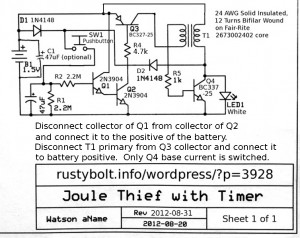
I’ve built an automatic shutoff timer into a regular flashlight, and into my Commercial Killer. Putting a timer into a JT has a very practical use: it saves the battery. I’m not sure why someone else hasn’t tried to do it, maybe just never occurred to them. I thought about putting one into a JT with the single 1.5V cell, but since the ones I’ve built use a Darlington pair, and I thought at first that it wouldn’t work at 1.5V. I went over the voltages and came to the conclusion that the Darlington pair was not a problem (but see my later comments).

The circuit works just fine when the supply voltage is 3 or 4.5 volts. The capacitor takes a couple minutes to discharge and the light stays bright. But the JT’s single cell has only 1.5V, which is too low. To remedy that, I decided that I would rectify the JT’s output to the LED, so I can get 3 or more volts to the 47 uF timing capacitor. That’s why I added the two diodes, D1 and D2. D1 lets enough voltage through to the capacitor to start the circuit, then the JT adds 3 or so volts through D2 to the capacitor.
Old Joule Thiefs don’t die, they just fade away – The LED doesn’t go out abruptly; it fades away over about a minute. The 47 uF gives about a minute and a half of bright LED, then it starts to dim. This gives you a warning that you have to press the pushbutton again to restart the timer. This cap can be changed or one or more switches can be added to allow the user to select the time. 100 uF should give 2 or 3 minutes. But some larger electrolytic capacitors have some leakage that can discharge the voltage even without anything connected, so don’t expect large capacitors to give an accurate timeout.
The circuit works fine at 1.5V, which is equivalent to a fresh battery. But there is only a little more than 0.1 volt across R4, and Q3’s base current seems to not be enough, because the voltage drop across Q3 is about 1/4 volt – it should be lower. The value for R4 may have to be reduced, but even at a lower value, if the battery discharges below 1.4V, the circuit may have trouble. I turned down the supply, and found that at 1.35V, the circuit works poorly and at 1.25V the LED is very dim. This is caused by the Q1 and Q2 Darlington pair, which requires a minimum of 0.6V at the collector.
My solution is to disconnect the collector of Q1 from the collector of Q2 and connect the Q1 collector directly to the battery positive. The voltage across R4 increased to 0.75V, and that allowed me to increase R4 to 1k. With this single change, the JT puts out full brightness with the battery voltage at 1.25V, and works to less than 1V. It is much more tolerant of a discharged battery than it was before. Now it will work okay with a Ni-MH rechargeable cell. Also the LED stays brighter for a longer percentage of the total time it’s on, and it goes out quicker.
Change for the better – But then I wasn’t thinking when I drew the schematic. My Blue Blinky and others used a circuit to control the JT, but they did not switch the whole current to the JT, only the bias current to the base. So I removed the primary winding of the coil from Q3, and connected the winding directly to the battery positive. Now only the bias to the feedback winding and then to the base is switched by the timer. The current through Q3 is dramatically reduced. I haven’t done it yet, but I can increase the value of R4 to a much higher value. something like 3.3k or more. I took a 3.9k out of the parts box and put it in, and it works okay; the LED lights brightly.
But an interesting phenomenon has now occurred. The currents in Q1, Q2 and Q3 have been reduced a lot, and the time has been extended. Before the LED was starting to get dim at 2 minutes and then no light at 2 and a half minutes. Now it hasn’t started to get dim at 3 minutes, and about 4 minutes it has dimmed noticeably, but not gone out. After another minute, the LED was still very dimly lit, but the supply current was very low. When I brought my finger next to, but not touching the Q1 and Q2, the LED lit up brightly. The currents in the circuit are so low and the impedances so high that it is now a detector of any hum or interference. I turned off the soldering iron and the LED went almost out. When I have my hand near it and I shuffle my feet on the carpet, the LED blinks. An electrostatic field detector? Weird!
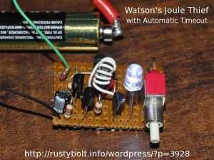
 Update Sept 1 – I assembled a second JT w/Timer on a piece of perfboard – the original was just tack soldered together. I used identical components except for Q3, which I changed to a 2N3906 since it now carries so little current (but the BC327, 2N4403, PN2907A or any other PNP will work okay). I built it to validate the design. It works as well as the original, and fits (minus the oversize pushbutton) on a board about the size of a postage stamp That switch was salvaged from the motherboard of a telephone PBX. When I had to push that reset switch, up to 200 phones would suddenly go dead(!) And they would stay dead for the next 5 or 10 minutes while it was rebooting.
Back to experimenting…


