default

2012-08-15 Joule Theif (sic) Meets ABHA Coil

I received a Google Alert for a Youtube video called “Joule Theif (sic) meets ABHA Coil!!” and I have some comments that I’d like to share, but I’m not going to put up with Youtube’s extremely lame text limitation of 512 characters.

The two batteries in series show 2.5 volts on one DMM, and I’m guessing that the other DMM is showing current, but after watching it a couple times, I didn’t pick up anything about what that current was.  It may have been the battery current.  If so, then 2.5V times 0.025 amps is 0.0625 milliwatts.  That’s a lot less than what a typical Joule Thief draws.  A typical JT draws 80 milliamps at 1.5V which is 120 milliwatts, about double what his is drawing.

I have to thank him for doing this interesting video. But if he reads this, I hope I don’t disappoint, because life is tough when you’re a JT, and it’s difficult to do the JT job efficiently.  He keeps on saying that the JT is amazing,  but he may not like reading the truth. A typical JT has an efficiency of 40 to 60 percent, or about half the input is lost and doesn’t get to the LED.  He doesn’t give the output current but I’m sure his JT circuit is not any more efficient than a typical JT.

He said that all 24 LEDs are in series, at 3.4 volts per LED.  That’s a total of 81.6 volts.  That’s awfully high voltage; the TIP31A is rated at a maximum collector voltage of only 60 volts (by the way, the G after the A stands for lead free or ROHS).  He should be using the TIP31C, which can handle 100 volts max.  It would be better to break the 24 LEDs into two parallel strings of 12 LEDs each for a maximum voltage of about 31 volts.

It’s much easier for a JT to convert a voltage from 2.5V to 3.4V than is is to convert from 2.5V to 81V.  The higher the conversion ratio, the harder it is for the JT.  That’s why I said that I’m sure his JT is no better than 40 to 60 percent efficient.  My guesstimate is that it is even lower than this.  Another very important point is connecting all the LEDs in series is not a good idea.  If one fails open, then the whole string will go dark.  It is much more reliable to connect the LEDs in series – parallel so that if one fails open, only a fraction of the LEDs will be affected.  If the lamp is to be used in an environment (such as a tropical climate) where the weather is wet, there is a high probability that there will be corrosion in anything electrical.  So choose a design where a single point of failure such as a single LED in a series string will not totally disable the light.

ABHA Coil

Okay, now for the mystery ABHA coil.  I’ve never run into this term, even though I have a lot of experience with RF and inductors.  It’s probably an acronym someone came up with to describe his method of winding the coil.  I’ll have to Google it and see what turns up.  I can say that after seeing how broad the field was, that this is not good for making an efficient coil.  When we wind a toroid, the donut shape contains the magnetic field so that very little gets outside, and this makes for a good high Q, low loss coil.  His ABHA coil obviously doesn’t exhibit this quality.  Update: I Googled it and watched a Youtube movie about the ABHA coil.  Looks like it’s from the same Youtube account.  I heard something, but it didn’t sound like any valid scientific explanation. He gave no valid measurements.  He compared two currents, but the current is only half of the power, the other half is the voltage.  When you measure the power output and the power input and then divide the power output by the power input, you will get a fraction that when multiplied by 100 gives the efficiency in percent. This movie had none of that.

Back to the original movie.  He talks about packaging the circuit up with a solar cell and selling it to third world countries where they have no electricity.  With a coil that big, it’s going to be really difficult to package it into a reasonable sized enclosure, and with an external field that is that strong, the magnetic field may be absorbed by the case or other parts if they are metal.  I also must mention that at least one other entrepreneur has already created a similar piece of equipment and is trying to introduce it to the countries without electricity (more on this in the note below).

I’ve given just a few of the many ways to improve the conversion efficiency of a conventional JT.  My ‘Supercharged Joule Thief’ circuit increases the efficiency to 70 percent or more.  It’s a simple circuit and I’m dismayed that no one seems to recognize its merits.  Could it be that once they have built a conventional JT, they are so dazzled and ‘blinded by science’ they believe it’s the be-all and end-all of lighting a LED from a single 1.5V cell?  Believe me, if they try the ‘Supercharged Joule Thief’ circuit they will never go back to the conventional JT again.

I googled ABHA coil and came up with more hits.  This one is just stunning.  I got more than halfway through this balderdash and gave up.  He takes 36 paragraphs to say nothing of any value.

Note: the justification for introducing a simple rechargeable light is to allow children in school to study at night after sunset.  At the present time, they have to use a kerosene lamp, and the fuel is expensive and pollutes the air in the house.  The rechargeable electric lamp would eliminate the pollution.

default

2012-08-14 Broken Duracell Charger

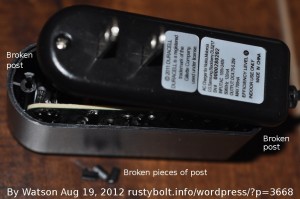
Not long ago I bought a Duracell charger for my cell phone.  It has various adapters to fit the different power connectors, in my case it was the Micro USB.  I connected my cell phone to it last night and plugged it into the wall, and this morning I went to unplug it from the wall.  Instead of coming out of the wall socket, the case separated into two halves, and the bare connections to the power prongs were exposed (remember the prongs were still plugged into the wall).  Yow!  My hand was right next to the live wires!  I didn’t get shocked, but I could have if I had been careless and let my hand move a little bit closer.

I carefully removed the case half from the wall socket.  This was not supposed to happen.  Not only is it a shock hazard, it could cause a fire if something came in contact with the bare connections.  Apparently when the case was assembled, the two screws were too big for the holes in the plastic posts, and the posts split.  When I went to unplug it, I did not exert excessive force on the case, I just pulled on it, expecting the whole case to come out of the socket like it should have.  Instead, the split plastic posts broke, and the two haves of the case separated.

I checked the Consumer Product Safety Commission for any recalls for Duracell, and found one: it was related to chargers but it was for a laptop computer, not cell phones (see screen capture).  I guess I was fortunate that all this happened when I was there and knew what was unsafe/hazardous, and took appropriate action.  Others might not have known and might have been shocked.  I suggest that if you have a Duracell charger like the one in the picture, you stop using it and ask for a refund.

default

2012-08-13 Thousand Watt Lamp

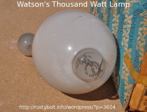
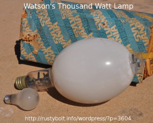
Bill told us he would like to Steampunk a large lamp, so I volunteered one of the ones I have in my garage.  It’s a biggie!  The regular 75 watt lamp is beside it in the pic.

I also have another one similar in size but shaped like the 75 watt lamp, because it’s incandescent.  I think it’s a 500 watt , but I’m not sure.  It’s boxed up in one of the many boxes I put in the garage when I moved last month.  I’m not sure which box, and most likely it’s buried in the stack.  But anyway, it’s clear, not frosted like the one in the picture.  I think that if the lamp is opened up, the frosting can be removed.  But then maybe it would look better with the frosting if it is being filled with LEDs.

The glass can be cut with a cutting tool.  But I learned a long time ago that there is another way to cut it.  A piece of string is tied around the joint where it is to be cut.  The string is wetted with a flammable fluid, I think lighter fluid was what was used, but I’m not sure.  The string is lit, and when it goes out, the glass will break cleanly if it is dunked in water.  I should google this and see if I’m correct.  Here is one person’s description of how it is done.

default

2012-08-12 Clear VHF Channels on a UHF Antenna

Last month I put an antenna strap mount on my chimney and put a 6 foot piece of 1 inch galvanized pipe in it.  Then I went shopping for an all channel TV antenna.  I had a UHF antenna, but I figured that I should install a decent VHF/UHF antenna.

I went to Radio Shack and the cheapest outdoors antenna they had was 85 dollars, and I figured since they’re always overpriced (the strap mount cost $30!), I could find one cheaper somewhere else.  So I went to Fry’s Electronics.  Their shelf said Channelmaster 3016 for $40 or $60, I forget which, but the shelf was empty; they were sold out.  I asked the clerk where I could get one, and they said another store in Fountain Valley.  A week later, I went to that store and they were sold out.  Oh, well.  Forget it for now.  Maybe later I’ll go online and order.

So I had a friend of mine over, and we went on the roof and installed the UHF antenna*.  I drilled a hole through the wall and ran the RG-6 coax through, and connected it  to an extension and to the TV.  I turned the TV on and the UHF channels worked great.  Then I flipped to the VHF channels, and they all worked okay, too.  An added bonus, I guess.

Sometimes when the signal is weak, the digital channels will just give a “NO SIGNAL” display on the screen.  It’s not like the old days when you could watch the analog TV channel with a little bit of snow in the picture; the digital TV receiver just doesn’t work.  And that’s what puzzles me!  I have not had any interference or NO SIGNAL at all on the VHF channels.  I had a few on one of the UHF channels, but it cleared up in a few days, which leads me to believe that the problem may have been at the TV station.

But here I am, watching the TV for the last few weeks, apparently defying the laws of physics by watching VHF channels come in clear on an old UHF TV antenna.  Strange, huh?

* If you’re going to work on the roof, get someone to be around to pick up the pieces in case you imitate Humpty Dumpty.  Safety First!

default

2012-08-11 1W LED Lifetime Test

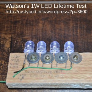
In late 2009 I obtained a few dozen of these 10mm 1 watt single chip white LEDs from a Chinese vendor on eBay.  My main intent was to see how long they would last in a lifetime test.  I attached four of them with screws and washers to a piece of wood, and connected them in series and up to a 9V AC ‘wall wart’ adapter.  I measured the current at about 130 mA – the current varies a bit with the AC line voltage.  The LEDs are 1 watt, and should be able to handle over 300 mA, but they are running at less than half that in this test.  The washers and screws act as heatsinks and the LEDs run warm but not hot.

I used these as a rather bright night light  but left them on 24/7 with the exception of a very few power outages from November 7, 2009 until this summer 2012.  In this photo they are all four powered on and putting out what little light they have left after a few tens of thousands of hours.  When they were first powered on, they were very bright and would have shown four bright spots in the surface in front of them, easily overpowering the light from the camera’s flash.  Now the four spots are not even visible, masked by the camera’s flash.  In my old blog I showed a picture of them pointed at the wall, along with the exact same LED, but new and unused.  The single new LED was much brighter than all four of these LEDs, showing that these have lost most of their light output over the 3 plus years they have been left on.   I can look directly into the lens and see the chip without eye strain, because the light output is so dim.  I would estimate they have lost 90 percent or more of their light output, but I can’t give an accurate amount because I did not have the luxmeter at that time. My conclusion is that they were relatively inexpensive and unfortunately I got what I paid for.

default

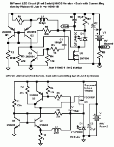
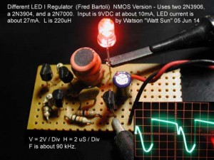
2012-08-10 Different LED DC-DC Buck With Current Regulation

I built this circuit, and it seems to be a lot more complex than it needs to be to do the job.

default

2012-08-09 Joule Thief Inductance – Too much? Too Little?

Kirk left me a comment asking how much inductance is too much.  I’ll try to go into detail as to how the inductance and other factors affect a Joule Thief.  First a couple things should be defined.  This discussion is confined to a conventional JT, with a single transistor and a coil with two windings: a primary winding and a feedback winding.  Also, the battery voltage is limited to a maximum of a single cell, which is about 1.55 to 1.6 volts when the cell is fresh, but averages about 1.5V during most of the cell’s life, then tapers off as the cell becomes depleted.  We will assume that the JT is designed to be run at 1.5V. Also the LED is a typical white or blue with a Vf of 3.3V.

The job the JT has to do is transfer a ‘bucket’ of electromagnetic energy from one voltage, 1.5V, to a higher voltage, typically 3.3V for a white LED.  The typical 5mm white LED works optimally at 20 milliamps, which, multiplied by 3.3V, equals 66 milliwattts.  So we want the JT to give the LED a ‘bucket’ of energy equal to 66 milliwatts, and in doing this, the JT itself will use somewhere around that much, as losses in the transistor, resistor, coil windings and core.  So, for example, the total power we pull out of the cell averages 120 milliwatts divided by 1.5V, a current of about 80 milliamps.  But the transistor is turned on only about 30 to 40 percent of the time, so the transistor actually takes a gulp of current of 200 to 250 milliamps.

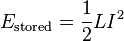
Ok, we go to the Wikipedia entry for inductor and read about it.  It says that Estored is equal to one half times the inductance times the current squared.  If you wind an inductor, the more turns it has, the more inductance it has and the more energy it can store.  But as you wind more turns on it, the resistance of the wire increases and the higher resistance reduces the current, since we are working with a fixed 1.5V.  If the wire resistance is doubled, the current is cut in half, but going by the above formula, the energy stored is 1/4 (current squared).  In order to increase the number of turns but keep the resistance the same, we have to use thicker, heavier wire.  As we add turns, the inductor grows from the size of a pea to the size of a grape, or even bigger, the size of a golf ball.  The inductor becomes so big that it takes up more space than the rest of the circuit.  This can be a problem if we have limited space.  Also the heavier copper wire costs more.

But instead, we decide to go the other way.  If we reduce the number of turns to half, the resistance is reduced to half, and the current can double.  But since the energy stored is equal to the current squared, the double current gives us four times as much energy stored.

So if you want your inductor to fit on the corner of your PC board and not take up the whole board, then it’s better to have fewer turns, lower inductance and lower resistance so that the 200 or more milliamps can flow and give us the stored energy equal to 120 milliwatts.  As we see above, there is nothing wrong with increasing the number of turns, as long as the wire is heavier so that the current does not decrease.  This means that the inductor will get larger, but if you have no problem with a large inductor, then the inductance can be as much as you want.  I’ve seen chokes that have more than 1 henry that would work, but the resistance of the winding would be high enough to limit the current to a few tens of milliamps or less.  The JT will draw lower current and the LED will not be full brightness.

So we have a choice of an inductor with a lot of turns of heavy wire, with a weight of several pounds or kilograms and is larger than your fist, but it works well in a JT circuit.  The frequency may be low, but your eyes can’t tell that the LED is not on all the time.  Or we can choose a much smaller inductor that fits on the PC board and has an inductance of a fraction of a millihenry, but the resistance is low, the current is high, the LED is brightly lit, and the frequency is several tens of kilohertz, but again the eyes can’t tell that the LED is not on all the time.  The choice is yours.  If you have no choice and have to use a very large inductor, then you’re limited to what you have.  But given the choice, most people would choose small, so it will fit on the PC board.

Type of Inductor
We can use a toroid core, because it can be small, have a relatively high inductance and a low resistance, and only a dozen or so turns, so it is easy to wind.  The inductor doesn’t have to be a toroid core, but they’re easy to find in old, not working PC power supplies or a CFL light.  I would just order some cores, such as the Fair-Rite 2673002402 for 11 or 12 dollars U.S for a bag of 100 from Mouser.

A few days ago I blogged some cores I scrounged from CFLs. They are small, and seem to have a good amount of inductance with some small wire, which is short so it will have low resistance.  For the neophyte, the CFL seems to be a cheap source of cores in small quantities.  The dollar store sells new CFL lights for a dollar, so you can get a toroid core and  several other parts from each light, making it a reasonable cost, readily available source for JT cores.  I used a small blade screwdriver to fit in the groove that is where the two halves of the case snap together.  A couple twists and it will start to come apart.  I snip the wires and voila!  I have the guts laying in my hand.  That sounds a bit unappealing, doesn’t it?

Conclusion
So the answer to Kirk’s question is really about how much compromise you have to make when it comes to cost, size, energy storage, resistance and construction of the inductor, such as toroid, bobbin, air core, etc. Most will make a decision towards the smaller size, so they will have to compromise in the amount of inductance. I’ve found that 100 microhenrys is a reasonable amount for a conventional Joule Thief, but this can vary widely.  The inductance can go below 100 uH, but you have to remember that as the inductance decreases, less energy is stored.  Also, the energy ‘buckets’ are smaller, so in order to keep the LED the same brightness, the frequency has to go up to transfer more of the smaller ‘buckets’.  The frequency can go up, but if it gets above a few hundred kilohertz, there is an increase in the chance that the frequency or its harmonics will cause interference with the AM radio band.

Another factor is the size of the wire.  I often use regular 24 AWG solid insulated telephone wire which can be removed from old telephone cable or even from cat5 cable (it’s awfully kinky, though).  It’s cheap (free!) and easy to find.  The insulation makes it thicker so fewer turns can be put on to a toroid core.  If enameled wire is used, the insulation is very thin and maximizes the number of turns that will fit on to the toroid.

Thus we have multiple factors that have to be considered when making these decisions.  Inductors allow the experimenter to customize their component by winding their own.  With the information I’ve given, the experimenter can make some informed decisions on how to best wind their own.

Back to experimenting…

default

2012-08-08 Two Closeby Earthquakes, M 4.5

Last night about 11:23 PM I was given a good shake while in bed.  The M 4.5 earthquake was a few miles east of Yorba Linda, which is only about 5 miles from where I was.

This morning at about 9:33, about 10 hours after yesterday’s temblor,  I was at work and felt a sharp jolt, which got everyone’s attention.  Again, this M 4.5 quake was a few miles east of Yorba Linda.

There have been a few more in the same area, but not strong enough to be felt.  Aftershocks?  Or foreshocks?  If so, expect a bigger one very soon. :-O

Update Aug 29, 2012 – I was at work, checking a computer under the desk, when another earthquake shook the building.  It was 1:31 PM, the earthquake was a 4.1 magnitude, and I felt it, and so did the other people in the room.  This earthquake was from the same location as the previous earthquakes.

default

2012-08-07 Voltage Booster With Stabilization Feedback

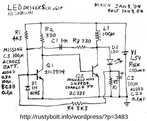
This circuit is from a bunch of drawings that I have from the years before I started drawing circuits on the PC.  It was drawn Jan 8, 2004 and built the next day.  The design is much like those found on websites and in electronics magazines with the exception of D1 and R4.  I’m not sure exactly what D1 and R4 are supposed to do.  D1 seems to be protection to keep the base voltage from going more than 0.6V negative, but it could also have other effects on the circuit.  R4 seems to be a feedback to stabilize the output.  As the LED current increases, the current through R4 increases and causes Q1 to go further into saturation, and changes the on/off time of the oscillations.  This should stabilize the circuit and make the light output less dependent on the battery voltage.  There is a slight penalty: the LED current flows through R5 and the voltage drop wastes a few milliwatts.

I don’t remember seeing the circuit in my collection of similar circuits – I may have disassembled it.  I have no further information on how well it performed.  Back then I spent a lot of time in the Usenet newsgroups sci.electronics.* and alt.binaries.schematics.electronic, and I may have found the schematic there.  Many of the people there were professionals* and were very helpful with problems.  But a few really bad apples spoiled the newsgroups for the rest, and the spammers were flooding many newsgroups with spam (there are many specialized forums that are moderated and don’t have the problems that the unmoderated newsgroups have).  Since I found that those forums had most of what the newsgroups offered, I stopped participating in Usenet.  Several years later I visited the newsgroups briefly and found that the same losers were causing problems, so I stopped and haven’t been back since. I also found that I was no longer wasting a lot of my time.

Back to experimenting…

*One was Winfield Hill who co-authored “The Art of Electronics”, an excellent text for the serious student of electronics.  Even though the book is expensive, I highly recommend it.


default

2012-08-06 Flasher, 5V Incandescent Lamp

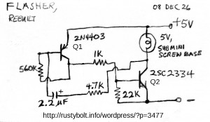
As it says, this was built on 26 Dec 2008, the day after Xmas.  It uses a high current, high gain transistor for Q2.  The 2SC2334 or KSC2334 comes in a TO-220 package.

I should remind everyone that the flasher is essentially a slowed down oscillator.  It can be used with a smaller capacitor to oscillate at a much higher frequency.  This is not going to work with an incandescent lamp because the heated filament is too slow to respond, but it can be used to dim an incandescent lamp.  The advantage is that Q2 is either fully on or fully off, so there is very little loss and very little heat in Q2.

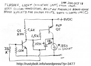
I found another flasher, and it also uses an incandescent lamp.  This is a #1850 low current light.  The 1.5k limits the base current to Q2 to about 3.5 mA; Q2 must supply 50 mA to the #1850 after the filament is hot, but much more than that when it’s cold.  So Q2 should have a moderate to high current gain and be able to handle more than 100 mA,  I believe PN2907A, BC327 or 2N4403 should do the job adequately.  Or better yet, a BD136, BD434 or SS8550 PNP transistors can handle more current and drive a brighter bulb.

© RustyBolt.Info/wordpress
CyberChimps