 In Jan 2009 I collaborated with Quantsuff and we tried different designs for a low voltage Joule Thief. The conventional silicon BJT Joule Thief (bipolar junction transistor) has a base to emitter forward voltage of about 0.55 to 0.6 volts, so if the supply is below this voltage it will not start. But once it gets started, it will run to below 0.5V, maybe down to 0.35V. We can change the transistor to a germanium, which is an ancient 1950s transistor technology no longer made. The germanium’s forward voltage is about 0.2 to 0.25 volts, so the germanium BJT Joule Thief will start up at half the voltage of a silicon BJT. But as I said, these are old transistors no longer made and difficult to obtain, and the reasonably priced ones can’t handle a large amount of current and power.
One idea QS had was to use a switch to charge a capacitor when the JT was off. Then when the switch was turned on, the capacitor’s voltage was added to the supply voltage, and the JT would start up. The supply voltage could be as low as 0.3 volts, and the added voltage would be 0.6V, enough to start the JT. Cool. But someone had to switch the switch every time it had to be powered up. About that time solar LED garden lights became cheap and experimenters like Bill Sherman were buying them, opening them up and experimenting with the parts. If you built solar garden lights with a half volt solar cell and the switch and capacitor to start them, you would have to walk around to every garden light to switch the switch to turn it on. Obviously this was not a very practical solution.
The Law of Diminishing Returns Another problem at low voltages was getting enough power to light the LED reasonably bright. Let’s say we have a JT that puts out enough current to the LED, say 10 milliamps, with the 1.5V cell supplying a current of 50 milliamps. The 1.5V times the 50 milliamps is 75 milliwatts drawn from the cell. The JT is boosting the 1.5V cell up to about 3 volts across the LED, or about doubling the voltage.
We want to run the JT at half that voltage, 0.75 volts, but we still want the LED current to be 10 milliamps. We lower the supply voltage down to 0.75 volts, but the current from the cell and the current to the LED drop dramatically. We have to do something to bring the LED current up to 10 mA, so we replace the 1k resistor that is used in the conventional JT with a lower value. This helps some. We look at what the JT needs to do the same job that it was doing at 1.5V. When the supply voltage is cut in half, the supply current needs to be doubled in order for the JT to draw the same amount of power from the supply. Therefore the supply has to see a load that is one quarter the resistance. Yes, the voltage will be half, and the current will be double, so the load has to be 1/4 the resistance in order to draw the same power. Also, the JT has to boost the voltage from 0.75 volts up to 3 volts, or four times higher.
We look at the components: the supply, the transistor, the coil, the resistor, the wiring (the LED has to stay the same; it can’t have a lower forward voltage). The transistor has to conduct twice as much current at half the supply voltage, so it has four or more times the demand put on it. The coil has to handle twice the current at half the voltage, so the DC resistance of the primary winding must be reduced to 1/4 to keep the losses down to the same level. This means the wire has to be much heavier to handle the higher current and lower voltage. And the coil has to boost the voltage twice as high as it did previously so it has a greater demand put on it. The supply has to supply twice the current, or 100 milliamps to the JT, so the demand has doubled on the battery. Also the resistor has to be reduced to 1/4 (or more) because the transistor has to handle twice the collector current, which means at least twice the base bias current, and at half the supply voltage. And remember, we have only reduced the supply voltage to 0.75V, which is half of 1.5V.
When we again reduce the supply voltage by half to 0.375 volts, the supply current again doubles to 200 milliamps. The demands again multiply exponentially, so that things that were insignificant before at 1.5V are now becoming really significant and can cause problems if not taken care of. An example is the size of the copper traces (‘wires’ or conductors) on the circuit board have to be much heavier to handle the greatly increased current. The bypass capacitors have to be much larger to handle the much higher currents. The length of the circuit board traces may become a problem because they add inductance, and may interact with the coil and capacitors. The resistor has to again be reduced by 1/4, so it is now down to 62 ohms (1/16th of its original 1000 ohm value). My whole point of this explanation is we are reaching a point where the Law of Diminishing Returns begins to eat away at our results, and it becomes much, much more difficult to do what seemed relatively easy at 1.5 volts.
MOSFETs I experimented with the MOSFET augmented Joule Thief using a 2N7000 and a 2N3904 BJT. It worked fine, but it would not start reliably below 0.6 volts. I brainstormed and came up with the idea that since the gate of a MOSFET does not need any current, only voltage, I could put a button cell in there and it would reduce the gate voltage to less than 1 volt. This worked well for the 2N7000 Joule Thief. But we really wanted to get the JT to start and run at voltages below 0.6V and also put out a reasonable amount of current, which the silicon and germanium JTs could not do at very low voltages.
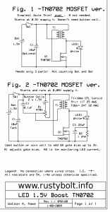
I ordered some TN0702 low gate threshold voltage MOSFETs. These are low power devices; they are not power MOSFETs. But one can put out enough current at low voltage to drive the LED of a Joule Thief to reasonably bright current. The first circuit I built with one was a MOSFET JT that did not need a resistor, and was the simplest Joule Thief possible, only three parts: a coil, a TN0702, and a LED (not counting the battery and on.off switch) (see Fig.1 of the schematic). I blogged this and it became one of the more popular of my blogs because the search engines gave it a lot of hits when people searched for low voltage Joule Thief.
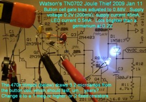
Considering the demands I pointed out above, the TN0702 worked as well as could be expected in the JT circuit I made (see the pictures). The extreme demands put on it at a supply voltage of only 0.2 volts made it impossible to supply as much LED current as a JT at 1.5V, but it did as much as it could, and I measured 0.5 milliamps LED current. That doesn’t seem like much but it was far greater than I had ever been able to do with a JT at a supply voltage of only 0.2 volts. The supply current was only 45 milliamps, but again that was much more than any germanium transistor was able to do (silicon transistors were useless – not able to go below a half volt).
The article found here (.PDF) explains the theory and construction of a DC-DC converter with an input of 350 millivolts (0.35V) and an output of 5 V for running a microprocessor or other device, meant to be supplied by a thermoelectric generator (TEG). TEGs are often made with Peltier junction devices, which are also used in small coolers that plug into the 12V car power. In this case the TEG was a thermopile.
Back to experimenting…


