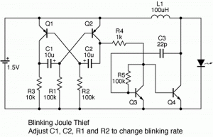
I was discussing with Aki (theledart.com) his JT blinker, which uses a single winding coil, two transistors for the “JT” V booster, and two transistors in an astable multivibrator to blink the “JT”. He asked me to include the schematic.
The first circuit boards that I had made from ExpressPCB.com used an astable multivibrator. I wanted to extend the battery life by turning the LED on for only a short time during the flash. I used ten times more resistance in one of the base bias resistors so that the astable MVB stayed on about 10% and was off for 90%. Assuming a flash rate of 1 second, the LED was on for about 1/10 of a second or 100 milliseconds (the actual flash rate was 1.2 per second). This cut the average battery drain down to ten percent of its full-on current and extended the battery life probably by ten times.
But then I built my Blue Blinky and on Dec 1, 2007 I put in a partly used AA cell. It ran for 21 months on that cell, much much longer than the flasher that used the astable MVB. I measured the on time of my Blue Blinky and the LED was on for only about 4 milliseconds, much shorter than the 100 milliseconds that the astable MVB was on. It was obvious that that was the reason why the Blue Blinky battery lasted for so long. Even though it was on a shorter time, the flash was still bright.
The Blue Blinky uses a two transistor flasher circuit like the ones in Bill Bowden’s hobby circuits. These have been around since the transistor was first made available commercially. The circuit was used in road barricades that had the yellow flasher light.
At that time, transistors were only made of germanium and could operate down to less than a quarter volt. Germaniums are no longer available and were replaced by silicon transistors, and since silicon transistors stop operating at a half a volt, the battery is not as ‘used up’ as it once was and still has a half volt in it.
Many experimenters want to ‘harvest’ that last half volt. They try to come up with some way of extending the Joule Thief down to below a half volt. I have already shown how to do that. But anyone can take two half volt batteries and put them in series, and then the Joule Thief will run them down to a half volt total, or 1/4 volt each.
About the Joule Thief part of the circuit – Aki said he likes a simple single winding coil. I found that I was spending more than a dollar apiece for the 100 microhenry chokes I was using in my early designs. Later I found that I could buy a Fair-Rite 2673002402 “suppressor sleeve” which is really a toroid core, for 12 cents apiece from Mouser. I then had plenty of telephone wire in my junk box, and all it took was two 6 inch pieces of red and green 24 AWG telephone wire (about a foot (30 cm) total), and about a minute to wind them bifilar around the toroid core. Voila! A Joule Thief coil with about 150 microhenrys per winding that costs 14 cents. You can also use this for a single winding voltage boost circuit and it’s a lot cheaper than buying prewound chokes. I think that an experimenter should be willing to invest a little ‘sweat equity’ into his or her projects. And it always helps if that sweat equity pays off in the long run by saving money.
But if you’re hooked on the chokes, you can make a conventional single transistor JT by using two chokes. The first choke serves as the primary winding, and the second choke is positioned next to the first and acts as the feedback winding. It picks up the magnetic field from the first choke and inverts it, and this is fed to the transistor’s base, just like the two winding coil. You have to have the second choke positioned the correct way; one way will work, the other won’t. If it doesn’t oscillate, then the position of the feedback choke has to be flipped end for end. Once they are working, it is a good idea to glue them together with silicone glue or hot glue so they won’t move apart. Tape or shrink tubing would also work. I personally think this is a poor design because I have never seen this used in any commercial equipment, and never seen it used in any experimenter’s JT on the ‘net. But it does work.
Conclusion – The results of my experiments show that if you’re looking for the longest battery life for your flasher, then it is best to use a circuit like the Blue Blinky that turns on the JT for a very brief period, so that the LED gets a high peak current during the flash, and the average current drain is very low. You can find more very low power battery flashers in Dave Johnson’s discovercircuits.com. Go here and look for flashers.


[…] read the article at Rustybolt Share Tweet wordpress plugins and […]