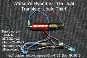
 I’ve been running some AA and AAA cells on a few Joule Thiefs that use silicon transistors until the cell gets down to about a half volt, then I switch the cell to a germanium Joule Thief and run it until the LED goes out and there’s typically less than a quarter volt left in the cell. Some of the AA and AAA cells are way, way out of date, like the 1990s and even a few from the late ’80s. Believe it or not, these still have enough juice in them to light up a JT fairly bright. But I’ve had some of them leak, so I decided I have to get rid of them, so why not run some JTs while I’m getting rid of them?
The solution to the leakage problem is to use a pair of small magnets to hold the wires on to the ends of the cell. If it leaks, the corrosion only affects the small magnets and usually can be scraped off the magnet so it can be reused.
But I wanted to get rid of having to switch from silicon to germanium Joule Thiefs. Why not combine them into one? Good idea.
I decided that an easy way to do this is to parallel one of each transistor. If the germanium is a PNP, then I’ll have to use a PNP silicon such as the 2N4403 or BC327. The emitters and collectors of both Si and Ge transistors are connected together. The existing 1k resistor to the silicon is still used, and another 1k resistor is connected to the second transistor’s base and the winding lead that’s going to the original 1k. See the attached photo. The BC327 silicon transistor (black plastic case) is nestled between the leads of the 2N404 germanium transistor ( larger metal case).
Downshift – When the cell has more than a half volt left, the silicon and germanium transistors will both switch current to the coil. As the cell voltage drops below 1/2 volt, the silicon stops working, and the germanium continues to switch current until the cell voltage drops below a quarter volt. Then both transistors stop, and the cell is thoroughly drained and ready for the trash can.
Also, the germanium transistor will start up with 1/4 volt from the cell, and the silicon transistor will then go along for the ride, idling in the background. The two transistors should give more current to the LED than a single transistor, but I haven’t measured the LED current yet.
I’ll have to convert a couple of the JTs I’m using and see how it works. Well, I’ve already done that, as evidenced by the mess of wires in the photo. I have some germanium transistors that are NPN so I won’t have to switch the polarity of the JT.
Another thought – I could add a third winding to the coil and put it in series with the existing feedback winding. The idea is the germanium transistor using the existing feedback winding would get the JT running when the cell voltage is less than 1/2 volt, and the added winding would boost the voltage to get the silicon transistor conducting even though the cell voltage is low. Another thought: use this added winding to drive the gate of a 2N7000 MOSFET, and see if the two transistors will run at very low cell voltages. Also, if the winding was isolated it could be rectified, filtered and the DC used to provide a several volt supply to drive the gate of a larger MOSFET. Essentially the idea here is to use the germanium transistor just for minimal current generation for supplying the higher voltage the larger switching transistor needs. But I have to remember that I have already done a similar thing with regular silicon transistors.
I did a few tests with ‘dead’ batteries. It works, giving a lot less light when the cell is below a half volt, but it drains the cell, which is my main objective.
Back to experimenting…