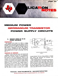
 I took a picture of this old application note from Texzs Instruments dated 1960. The circuit uses a germanium transistor, and adds a third winding to the coil to get high voltage (800 volts). If this third winding is removed and a LED is placed across the Q1 collector and emitter, and the supply voltage is reduced to less than the LED V, then it would be essentially a Joule Thief.
They used two resistors in a voltage divider to give the transistor base bias current. One thing that we should remember is that the germanium transistor could have an emitter to base reverse breakdown voltage as high as the collector breakdown voltage. Today’s silicon transistors are typically rated for 5 or 6 volts, not any higher. This is not a problem when the supply voltage is only a volt or two, but if the supply voltage goes above 5V, then the circuit could put the same negative voltage on the base, so the transistor must have some way to protect it from excessive reverse E to B voltage. The ratio between the windings can be changed so that the feedback winding gets a reduced negative voltage. Or a few diodes or LED can be put between emitter and base to shunt excessive voltages. However this wastes some power, which is not desirable with a battery operated circuit.