default

2012-11-12 1.5V Joule Thief -Blinks LED

I received a Google Alert with a link to a Youtube video showing a blinking Joule Thief and its schematic.  I examined the schematic and found that the collector of the PNP was connected to positive, and the collector of the NPN was connected to the negative.  These are opposite to the polarity required for these transistors.  I left the author a comment about this but his reply said that his schematic was correct.

So I decided that I should build it to see if it would work.  I tack soldered it together using the same parts except for the choke, which was 180 uH, higher than the 100 uH in the schematic but it should not make any difference in the performance.  In the photo it’s easy to see the parts; it’s laid out like the schematic.  I did not include the optional CdS photocell, because it would not work in a lit room and I didn’t want to work in the dark.

With the power supply set at 1.5v and connected as in the schematic, I saw no light from the LED – I didn’t expect to.  I swapped the positive and negative supply leads to see if it would work, but I saw no light from the LED.  My conclusion is that the circuit will not work as shown in the schematic.

Update Nov 14
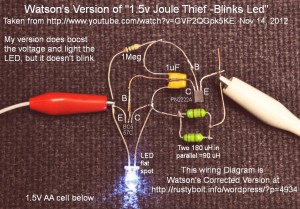
I built a second circuit (see photo) and reversed the two transistors as he discussed in the comments.  This is backwards from what the schematic shows in the video.  It does work, it boosts the voltage and lights the LEDs.  However it does not blink.

While I was handling the bare circuit, it started blinking.  I found that if I put my finger on the base and collector leads of the BC557, it will blink.  I’m experimenting with some resistors to see what value works well.  I tried a 1 Meg and the LED just kept on steady.  I tried a 470k and it blinked but it seemed like it want to still go on steady.  I tried a 220k and the blinks were very short and faster, but also much dimmer.  I think it might be a good idea to put a 470k trimpot in there and adjust to see what’s the best value, but I don’t have one at hand right now.  I’m guesstimating that a 390k might be a better choice.  I found a 670k pot and put it in series with a 68k and soldered them across the base to collector of the BC557.  The blinks get quicker and dimmer as I turn the pot from max to min, so I would put a 680k resistor there and try it for awhile.  Even though this maximizes the flash brightness, the flash is still very dim and I can look into the LED when it’s blinking and it doesn’t do anything to my eye.  I would guesstimate the LED current is much less than 1 milliamp when it’s flashing.  Thus the battery life will be very long, maybe several years.

Back to experimenting

default

2012-11-08 Switching Method For V Boost With Timeout

I started out using a single pole, single throw pushbutton switch from an old mouse for the switch on my Joule Thief with timeout circuit.  But I changed it to a double throw switch.  It’s simple to use the single throw switch to charge or discharge the timing capacitor and start the timeout.  But if the switch is unprotected and gets activated accidentally, then it will never allow timeout and the battery will be wasted and eventually go dead.

To prevent this, I changed the switch so that if it is pressed, the capacitor is charged but the circuit is not activated.  When the switch is released, the capacitor is then connected to the circuit and the timeout begins.  If the switch is accidently pressed and held, the circuit will never be activated and the battery will not be discharged.

The pushbutton switch comes from an old ball mouse and already has the double throw terminal.  The NC or normally closed terminal connects to the circuit, the NO or normally open terminal connects to the charging or discharging voltage, and the common terminal connects to the capacitor.  This is all a simple matter of rewiring the switch, and does not require any additional parts.

This switching method applies to any battery operated circuit where there is a possibility of accidental discharge.

Back to experimenting…

default

2012-11-07 Not Rusty Bolt Joule Thief – Really!

I was reading the comments in this Instructable and found a comment by Colin55 (Colin Mitchell of Talkingelectronics) showing a Joule Thief circuit that used a bolt and nut for a coil form.  He wound 200 turns on the bolt for the primary winding and 40 turns for the feedback winding.  One thing I think is a big mistake: he used a 9V battery, which is far too expensive and could be replaced by one or two AA cells for a small fraction of the cost.  Also by rearranging the 12 LEDs in series – parallel, the 9 volt Joule thief circuit could be replaced by a few resistors and it would even be more efficient.

But back to my circuit.  I decided that I should try to replicate the coil, even though I would definitely not replicate the circuit.  Instead I would use a conventional Joule Thief circuit with a 1.5V cell (or power supply).

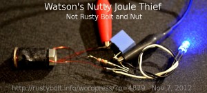
I scrounged a 1/4 inch by 1 inch long carriage bolt and nut – this duplicated the coil shown in the link, and wound a few layers of black electrical tape over the threads to prevent them from touching the wire and doing damage.  I then wound 40 turns of 28 AWG enameled wire onto the bolt, and brought out the loop of wire.  I continued to wind the remaining 200 turns onto the bolt.  Then I covered the whole winding with some more electrical tape to protect it.  The 200 turn winding measured 160 uH and the feedback winding measured 4.6 uH.

I tack soldered a conventional JT to the coil.  I used the typical PN2222A transistor, a 1k resistor and the light blue ‘box’ is a 0.22 uF capacitor across the power supply leads, optional but its use is a prudent addition.  The LED was a blue 5mm.  I didn’t show it in the picture, but I added a 1 ohm resistor in series with the LED lead, so I could measure the LED current.

Results

I connected it to the power supply which was set at 1.5VDC.  It flashed on and off erratically, it didn’t want to stay on.  I lowered the voltage down to 1.25V and it became stable and lit the LED constantly.  I measured the LED current and got 4.8 mA.  I increased and decreased the supply voltage, and I found that when I went above 1.2V the LED current went down, which is contrary to what one would expect.  I backed off to 1.2V then went below, and the LED current began to go down.  So there seems to be a broad optimum point at 1.2V where the LED current stays at 4.9 mA.  This anomaly is something I’ve never seen it the dozens of previous JTs I’ve experimented with.  The supply current at this point was 62 mA and the frequency was 63 kHz.

The typical conventional JT that uses a toroid for the coil will draw 60 to 80 milliamps from the power supply and put out about 17 milliamps to the LED, for an efficiency of about 50 to 60 percent.  This Joule Thief is drawing 62 milliamps, low but typical, but putting out less than one third of the current to the LED, which is very inefficient.  The obvious explanation is the coil, for it’s the only component that is different from a typical JT.  This coil uses a solid iron or steel core, with no laminations or powder.  To me this is the reason why it wastes so much power and is so inefficient.

Back to the optimum point.  I think that the reason for this anomaly is that the coil inefficiency causes losses to increase as the supply voltage and current increases.  It could be caused by core saturation.  The difference in the turns ratio (not 1:1) could be a contributing factor  In any case, the conclusion I come to is that this coil is a very poor design even though itt does work, but the coil has so much loss that it should not be considered when building a Joule Thief.  An alternative is to wind the wires onto an air core coil.  This is done by winding the wires onto an AA cell, then removing the cell and tying the coil with wire ties, tape or even dental floss.  This coil will be much less lossy than the steel bolt and nut.  And you don’t have to use the not so rusty bolt and nut, saving you money (or preventing your gate from falling of its hinges because you stole one of the bolts to make your coil!)

Back to experimenting…

default

2012-11-06 Election Day! What else is new?

Man, will I be glad when this is over.  My recyclables trash can is overloaded with all the flyers with which we’ve been bombarded for the last  few weeks.  Yet I have not seen a single flyer for the presidential race.  It’s like America’s most populous state doesn’t even exist as far as they care.  Well, there have been visits by the president for a thousand or more dollars a pop fundraising activity, but only the wealthy can afford that.  Why do a few states like Ohio and Iowa get to decide how the election is going to turn out?  I think it’s unfair.  But then the whole electoral college thing is unfair.

It just goes to show that “We have the best government money can buy.”

Update the morning after – It looks like the citizens of California have enough common sense to scuttle the propositions that were financed by Big Money.  The Calif Fair Political Practices Commission found that $11 milllion was illegally funneled into Prop 38 by out of state interests which laundered the money.  This prop was soundly defeated.

Prop 32 also was defeated, another one of those propositions that was financed by Big Money.  The media reported that this proposition was similar to two other earlier propositions which were defeated.  It seems that Big Money will continue to attempt to use California’s initiative process to pull the wool over the eyes of its citizens.  Hopefully the truth will prevail in the future.

The Prop 37, labeling of genetically modified food, was defeated.  My view is that since 70 percent of all food is genetically modified, it seems that if this proposition had passed, almost all foods would have to be labeled as GM, which doesn’t help people who wish to avoid GM food, since it would be extremely difficult.  Most foods have ingredients that use corn or its products such as high fructose corn syrup.  What are you supposed to do?  Quit eating altogether??

I would have liked to see the proposition abolishing the death penalty passed in Calif., but it was defeated.  Death row inmates spend decades on death row, and waste millions of dollars of taxpayers’ money while they automatically appeal their sentence.  In China, when a criminal is sentenced to death, they execute him by the next day.  No waiting around for the sentence to be carried out.  We have to look at other civilized countries.  Many of those countries have abolished the death penalty.  Why shouldn’t we?  It would save the state a lot of money.


default

2012-11-05 Ultra Simple Joule Thief Replication Video (sort of)

I received a Google Alert which linked to this Youtube video which consisted of about a minute of nothing else but a schematic of a circuit, with a lot of background noise.  The circuit consisted of a single transistor with a coil, capacitor and 68 ohm resistor, and of course the LED.  I tack soldered the circuit together with the same components, except for the 100 uH choke, which I instead used a 180 uH choke.  The transistor is labeled 2N2222, which comes in a metal package, but the picture showed a plastic package, which is actually a PN2222A or MPS2222A.

I set the supply at 1.5V and the LED lit up but not very brightly.  The current was about 12 milliamps.  I measured the voltage drop across the 68 ohm resistor; it measured 0.8V, more than half the supply voltage.  Since the whole supply current goes through this resistor, over half of the power is wasted in this resistor.  This makes for a very inefficient Joule Thief.

The frequency meter measured an extremely high 700 kHz, in the middle of the AM broadcast band.  This is a bad place to be since it interferes with the radio stations.  I have a strong suspicion that since the circuit includes a choke and capacitor, it actually is oscillating as a tuned circuit, not a true Joule Thief where the coil alone is producing a back EMF to light the LED.  I cannot confirm this because I still have not found the box where I packed my digital oscilloscope when I moved.  I haven’t even fired up the windoze PC that it was connected to.  I opened up some more boxes this weekend so I’ll eventually get to it.  I would assume that if the 180 uH choke was changed to the 100 uH, the frequency would be even closer to the middle of the AM BC band.

default

2012-11-04 Philips 5.5W LED MR16 Flood Light

I bought a Philips 5.5W LED MR16 spot light (.PDF) for about $20.00.  It puts out 300 lumens of warm white light.  The light needs 12VAC, and the base has two pins spaced about 0.3 inches apart, which fit perfectly into a screw terminal.  I’m using it above my workbench for illuminating the circuit boards or whatever I’m working on.  I used a 9VDC unregulated wall wart adapter for power, and soldered a green terminal strip onto a short length of wire, with a 5.5 by 2.5 mm power jack to accommodate the wall wart’s plug.

The light’s body is made from metal and it does get rather warm, but nowhere as hot as a halogen bulb.  I like the bright beam of light, very little goes to the side because of the reflector around the four LEDs.  The adapter says its output is 9VDC; the meters measure 8V, but the LEDs are very bright.  The light’s package says the light is dimmable.

I’m thinking that these 5.5W spot lights would make a good replacement for some other task lights I have.  Problem is they have to have an adapter or transformer to get down to 12V.  I need to find out how much power is wasted in the adapter or transformer.  I would not want to replace an 8 watt light with a 5.5 watt light if the adapter or transformer wasted 3 watts, so that the 5.5 watts plus 3 watts add up to 8.5 watts or a half watt more than the 8 watt light.  There may be other factors, too.  For instance any additional devices used to control the light, such as a dimmer or wireless switch, which would add to the wasted power.

I’ve been getting most of my LED light bulbs from Home Depot (I’ve bought four Philips L Prize LED lights, total $100).  I think they have their own less expensive brand name EcoSmart.  When I look at the shelves, the lights I see left are all daylight white.  Seems that they are perpetually out of stock on the warm white Ecosmart LED lights.  No matter, though.  The Philips lights are more expensive but more than pay for themselves over time in electricity savings.  The Philips L Prize lights are $25 but save much more than that over a decade or so.  I checked the ‘net and the cheapest I could find them was $33, so I think I should have bought more when they were on sale.

One important point that people fail to recognize.  The L Prize lights are dimmable.  When you dim a regular incandescent light, the light gets very amber, until it’s more reddish than one would like.  This does not happen to a LED light; the light stays the same color, and the lamp dims to a lower light output.  We get the best of both worlds: lower light output and light that’s the right color.  And we save a lot of money while we’re doing it.

default

2012-11-03 Watson Is Back! Crime On Campus

Well, my website and blog is back up, to Oct 28.  I can’t remember if I blogged after that, so I’m guessing that I may have had one or two, or even none, but I can’t remember what they were.  If anyone has seen one between Oct 28 and Nov 3 and remembers, let me know and I’ll try to recreate it.

All I know is the web hosting service got hacked , files got deleted and lost thousands of websites.  Sadly, vandals don’t always do it in the Real World.  Which reminde me of Friday after work.  A few of us got a demo of our recently installed security camera system.  More than a hundred cameras were installed around campus.  The administrator showed us the camera looking over the bike rack.  This bike thief comes up with a back pack, puts it on the ground and kneels down beside a beach cruiser.  He pulls out a bolt cutter and cuts the cable, but someone walks by, so he hides the cutter.  A few secfopnds later he’s back at it, and succeeds in cutting the lock, which goes into the back poack along weith the cutter and away he goes on his stolen bike,.  Luckily all of this is captured on video, and his picture is going to be on a rap sheet at the police, emailed out to everyone and posted around our campus.

What was even more incriminating was the tagger who drove up to a sign, got out of the car and scribbled his graffiti on the sign.  Then he got in the car, drove away and his license plate number were clearly visible, to give the cops a clear indication of who done it.

So the video surveillance system is already earning its keep, catching thieves and vandals in their act – at night too with the infrared illumination.  Santa Ana has a reputation for being a high crime city, but our campus has been relatively free of crime considering its location.  We will be even better off now that the surveillance system is working.

default

2012-11-02 Cerruzi’s “A History Of Modern Computing”

I got this paperback book on Amazon used for a very reasonable price.  Unlike the book “Bit By Bit:…” by Augarten which covers ancient history, this book starts off with the 1945 to 1956 era and because it’s the second edition, ends in 2002.  It  is not a technical book, but delves into the people and companies that designed and made the computers of each era.  I especially liked the chapters that covered the minicomputers, because they were not so well known but they led to today’s microcomputers on our desktop.

The author touches upon ‘the chip’ and its effect on the computer.  Kilby and Noyce get their fair share of attention.  Also discussed is the effects of the legal wranglings between the big players such as AT&T and IBM.  It has quite a few pictures, from the Univac to the Apple Mac.  There are extensive references in the notes to the chapter in the back of the book, which is over 450 pages in length.

Back to reading…

default

2012-10-31 Sound Level Meter

The schematic found here looks to me like it could be a good sound level meter with a few changes.  One thing that it has going for it is the meter is inside of the feedback loop, so it will have a linear scale at low levels.  Some meters don’t and the forward voltage of the rectifiers causes the scale to be distorted at low levels.

One problem it has is the coupling between the microphone and the opamp.  The schematic shows a polarized electrolytic capacitor as the coupling capacitor.  The problem is that every electret condenser microphone will have a different voltage drop across it when connected to this circuit.  One ECM might have 4.5 volts or more across it, which would be ideal, since there is 4.5 volts on the negative side of the coupling cap and the cap would be correctly polarized.  But another ECM might have less than 4.5 volts across it, which means that the cap’s positive terminal would be negative in relation to the other end, and the cap would be polarized incorrectly.

The easy solution is to replace the capacitor with a non-polarized capacitor such as a 1 uF plastic or disk capacitor.  Then the polarity doesn’t make any difference.  But there’s a much better way to do this.

Just remove the two 10 k resistors R1 and R2.  Connect one end of a 100k resistor to the junction of R3 and C2.  Connect the other end to the junction of R5, C1 and the ECM.  When the circuit  is first turned on, the R5 will supply a small amount of current to charge up C3 to the same voltage as that at the ECM.  Since the opamp is a FET opamp, the inputs don’t require any current and the voltage across C1 will be zero.  This saves one resistor, and the circuit can still use an inexpensive electrolytic for C1.

Back to experimenting…

default

2012-10-30 Solar Powered V Boost For Garden Light

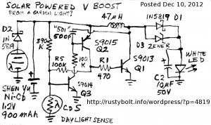
I drew this schematic years ago before Switchercad III or whatever schematic drawing package was available.  It’s a three transistor design; one transistor inverts the photocell’s voltage so it shuts off during the day.  The other two transistors make up the V boost circuit.  The S9013 is a good transistor for this, but a better one would be the S8050.  This S9013 has six gain ranges, from 64 to 300, which isn’t very high.  But it will handle a half amp current – about the same as the 2N4401.

The single AA NiCd or NiMH cell needs about 1.4 volts to fully charge.  Adding the half volt drop across the D2 diode, the total comes to just under 2 volts, so the solar photovoltaic cell has to put out current at up to 2 volts.  That means it must have at least four half volt cells in series.

Someone reckoned that the circuit should not need the CdS photocell because it already had a daylight sensor: the solar photovoltaic cell itself.  So many circuits do not have the CdS daylight sensor.

Back to experimenting…

© RustyBolt.Info/wordpress
CyberChimps