default

2012-12-18 Replication of “Any Value Joule Thief”

I watched this Youtube video where he replicates a circuit from an Instructable on designing an “Any Value Joule Thief”.  I read the instructable, and found that the claims made by the author seemed far too optimistic.

The Instructable goes through multiple calculations to arrive at values for the components in the schematic.  In the video, he uses a 1.2V rechargeable battery and claimed that the circuit could put out hundreds of milliamps to a high power LED.

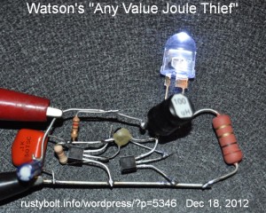
I’d like to remind you that this two transistor V booster is not a true Joule Thief.  In the picture, I show my replication of the circuit.  I used PN2222A NPNs for both transistors.  The other components are the same values that were given in the schematic.  The big resistor on the right is the 1 ohm current sensing resistor used for measuring the current through the LED.  The LED was a half watt 5 chip white 10mm LED capable of handling 150 milliamps.  The 100 uH choke had a DC resistance of less than 1/2 ohm.

My results were as follows.  I used a supply voltage of 1.5 volts, not 1.2 volts as shown in the schematics (this should increase the LED current, giving better results).  The supply current was 160 mA, the LED current was 51 mA, and the frequency was 98 kHz.  At 1.2 volts supply the LED current dropped down to about 42 milliamps.  This is about half the LED current of the 2 transistor “JT” circuit I blogged last week.

I thought that it might help if I removed the 100 nF capacitor which was across the Q1 (the orange blob between the clip leads).  I unsoldered it and the LED current jumped up to 74 mA at 1.5V, and the supply current increased to 290 mA, and the frequency jumped up to 216 kHz.  I’m not sure what the reason was for using this capacitor.  The 100 nF capacitor was damping the switching and slowing down the circuit.  It obviously performed better without it.

Instead of the 100 nF, I tried a 47 nF, but it still damped enough to dim the LED a bit.  I then tried a 10 nF, and it dropped the frequency 40 kHz and the LED lost only 2 milliamps, from 76 to 74 mA.  So a 10 nF is about the most that the circuit can handle without suffering too much.

I tried a variable capacitor across the 68 pF capacitor.  But no matter what setting it was, from 5 to 140 pF, the LED current went down as the capacitance was increased.  So 68 pF or less may be the optimum value.

The  one thing I haven’t done is switch the output transistor.  This PN2222A is capable of driving a regular 5mm white LED at full brightness.  But when pressed to drive a high power LED, it cannot measure up to the task.  It is quickly becoming apparent that the circuit has its limits just like others of this kind, and that no matter what calculations say, if the transistors are just average, the output to the LED will be just average.  A good choice would be the transistor I used in the blog I linked to in ¶ (paragraph) 4.

default

2012-12-17 IRF9Z34 Not The Same As IRLZ34

I ordered some IRLZ34 MOSFETs from Futurlec and they finally arrived, shipped from Hong Kong.  I took one out of the bag and it was marked IRFZ34.  What!?!?  I ordered IRLZ34, not IRFZ34!!  I took the rest out of the bag and I counted 33 of the IRFZ34, and 2 of IRF9Z34, which are not only the wrong part, but the wrong polarity!  Someone really screwed up, and mixed the wrong parts together!  I emailed them, and they promised to send me replacements.  But they ran out of stock, most likely because they checked the ones in their parts bin and found that most of them were the wrong part.  So they are going to ship me 18 replacements and give me credit for the remaining 17 they couldn’t replace.

This should make everyone aware that the parts companies do make major mistakes, and when you receive the parts, you should check a good percentage of them to make sure they’re really what you ordered.  I’ve had the same problem with Mouser.  They have also sent me parts on tape, where I could hold the two different part up and see that one tape of 50 capacitors, for example, was obviously shorter than the other tape of 50 capacitors.  That’s an immediate clue that there’s something wrong.

Back to counting parts…

default

2012-12-16 Quick And Cheap Joule Thief Light

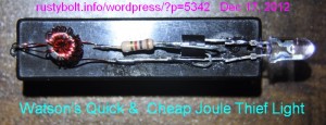
I blogged a similar light recently, but I didn’t get a good closeup picture of the parts laid out on the back of the AAA cell holder.  This time I got a good photo of it before I coated it with clear silicone sealant (I did get a good closeup, it’s in the linnk above).  I did not include an on/off switch because I figure these are made for a single use, and will be kept around in some drawer and possibly disposed of soon after use.  And I’m too cheap to spend $2 or more (USD) for a switch that actually costs more than the rest of the light.  I just cut a small piece of heavy paper or cardboard from a cereal box or whatever and stuck it between the battery and the contact.  When I need the light, I just pull out the paper.

Which brings me to the cost of the parts.  The LED was somewhat expensive, since it’s a Nichia that I bought a long time ago and probably cost a dollar.  Today anyone can get 9 of them in a cheapo flashlight that costs $2.00 (See Note).  The PN2222A transistor was less than 5 cents or five dollars for a bag of 100.  The resistor was pulled from a board, but they’re about 2 cents or $2 per hundred.  The toroid core was from Surplussales.com and cost about $.25, (ICH T231212T) and the wire was 30 AWG and cost very little, probably a few cents, since a quarter pound reel was about $15 but there are over a thousand feet of wire on it, and I used only about a foot.

Back to waiting for the silicone seal to dry so I won’t get sticky fingers from handling the light.  😉

Note: Some might wonder why I would pull apart a good flashlight (torch) with 9 LEDs to make one with 1 LED.  Well, the 9 LED light gobbles three AAA cells at a time, and doesn’t run very long on a fresh set of 3.  I have bought several of the Fenix LD01 flashlights, and they put out so much more light and use only a single AAA cell, and they’re so small I have one of them on my keychain.  So I will not use one of these cheapo flashlights, I just take out the LEDs and scrap the rest.  I tried using one of them for some other project, but after a year or so the plastic case became sticky and gooey, and melted into whatever it touched.  It was making a mess, so I don’t leave them around anymore.  Besides, I now have a single cheapo light that fits just about anywhere and runs off a single AAA cell.  And I’m proud to say I made it myself.

default

2012-12-15 Nutty Makeshift AAA to AA Cell Adapter

I bought a few bricks of 40 AAA cells at Fry’s, mainly because they were only $4.20 each, or about ten cents apiece – that’s cheap!  But I really needed AAA cells because of all the Fenix LD01 and similar flashlights I now have.  But I have so many AAA cells that I’ll never be able to use them up by their 2017 expiration date.  Unless…  I start substituting AAA cells for AA cells in low current devices like my Blue Blinky flashers.  So I had to come up with an adapter.

I bought a handful of AAA to AA adapters from Dealextreme; each one is a plastic snap apart case with a metal button on one end to extend the length.  They’re not bad, but they’re not available at the local store like the ones I made below.

The AAA cell sill fits into an AA cell holder, but it’s too loose and may fall out.  So I needed a metal spacer to go between the AAA cell and holder to take up most of the room and make the spring pressure high enough to hold the AAA cell securely.  What have I got plenty of that’s about that size?  A NUT!  Yeah, a nut from a quarter inch screw is thick enough to make the spring tight.  But I have only a few 1/4″ nuts.  But Burt used to tell me, “There’s no shortage of nuts around here!” and he was right.  So I looked into another screw drawer and found that I had plenty of 8-32 nuts.

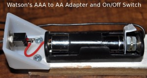
I grabbed a few and tried them between the AAA cell and the AA holder.  They worked good enough, so I took ’em out and put them on a burn proof surface and soldered them together.  After cooling off, I put the pair of nuts back into the AA holder along with the AAA cell, and that left me only one thing to do: make the on/off switch – see the photo.

I took a scissors and cut out a section of the side of a plastic pudding cup.   This L shaped section included the rim and part of the wall.  The wall  is the part that goes between the battery contact and the holder, and the rim acts as a finger pull tab.  It can also be seen in the picture.  It fits nicely between the side of the battery and the holder during use.

I wrapped enough black electrical tape around the middle of the AAA cell to help center it in the holder so it makes good contact.  But with the nuts in place, the battery is secure enough without the tape.

One thing I noticed about AA and AAA cells in general: different manufacturers make them different lengths.  One may be several millimeters shorter than another.  I noticed that with the two #8 nuts, the spring was compressed down to its minimum, and the AAA cell just barely fit.  With the two #6 nuts, the spring isn’t so compressed and the cell fits snugly but not tight.  So I may choose the #6 solution for most of the holders.  But the #6 nuts are smaller in diameter and tend to fall down and make contact off center with the spring.  But the holder still works okay.

Many of my projects have low enough battery current that will allow the AAA cells to be used and still have a reasonably long battery life.  The only problem is that some battery holders may have four cells, which means I’m going to be soldering a lot of nuts together!

Back to nut soldering…

default

2012-12-14 Watson’s Pancake Joule Thief

I received a Google Alert for a Youtube video from Mongrel Shark showing Joule Thiefs with his version of Tesla’s Pancake coils.  He refers to and gives the number of the patent Tesla had on this pancake coil (I haven’t read it yet).  He used two coils, each with its own Joule Thief.  For some reason he connected them in series, possibly because they don’t use a resistor and the current would be excessive if a single JT was connected.  However he did say that the battery had to be “flat”, which presumably means that it is dying or nearly dead.  The problem here is that the battery voltage is constantly changing, dropping as the battery dies a slow death.  This makes it very difficult to make comparisons because  the results, even between the same test. will not be the same after a few minutes have gone by.  It would also be a great help if he gave the supply voltage at the start of the test, just so we know how “flat” the battery really is.

My Version

I wound about 16 feet (5 M) of 18 AWG speaker cord onto an old CD, spiral wound and in a single layer.   The inductance measured 33 microhenrys.  33uH is below what I would have liked it to be; I would have wound more wire to get it to about 100 uH but I ran out of wire and space on the CD.  I will have to look for some thinner speaker cord, maybe 24 AWG, so I can get more turns on the CD.  I used wide masking tape to hold it together; duct tape would have done the job as well.

I used a BD433 NPN power transistor in the conventional JT circuit.  Instead of 1000 ohms, I used 330 ohms to get a lot more base bias current and more power.  The thin cord going off to the left (one wire has a small red sleeve) goes to a 24 blue LED strip about 10 inches long that is rated for 13.8 VDC.  This serves as a load so that the voltage across the BD433 doesn’t become excessive.

I had an air core coil from a previous JT experiment, made by winding two wires bifilar onto an AA cell, then taping the coil up and removing the cell.  I connected its two windings in series, which measured 155 uH.  I connected two white LEDs in anti-parallel (cathode of one connected to the anode of the other)  across the two windings.  This became my magnetic field sensor. I’m going to have to try others, since this one isn’t very bright.

The circuit draws over a half amp at a smidge over 1 volt.  I couldn’t get the supply to go any higher because it’s a half amp supply and it is going into current limiting.  Even so, the BD433 gets just barely warm, but the LED strip is not very bright, like less than ten percent of its full brightness.  The frequency was 30 kHz.  Only one of the LEDs lights on the coil; which one depends on whether the coil is positioned up or down – flip the coil ver and the other LED lights.  But neither one lights brightly; the LED current must be a fraction of a milliamp.

I made another sense coil, about the same as the first one except the inductance was 133 uH.  I used a single LED and found which way was brightest.  I also used a coil wound on a ferrite bobbin, which measured 142 uH.  It seems to concentrate the magnetic field more and may be a bit brighter than the others.  However the difference may be caused by the LED.

Back to experimenting…

default

2012-12-13 Important Things Happened Yesterday

Yesterday, the 12th day of the  12th month of 2012, important things happened in my life which were not made a part of the public record, but were still very important to me.  Why am I saying this?  It seemed that many people thought that yesterday was going to be the end of the world according to the Mayan calendar.  Well, earlier in the year, someone wrote that this prophesy was not based on anything credible, because the Mayan calendar only came to an end and it just meant that the calendar would then start over again, after the end.

One of our co-workers got married yesterday, at the stroke of 12 midnight, on 12-12-2012.  I’m not sure what their reason was for this.  But everyone can’t turn back the hands of time.  Yesterday was the last chance.  There is no thirteenth month in the thirteenth year, next year, in 2013, so that was the last chance.  Did it make any difference to me?  Hey, I did some very notable and important things yesterday, that no one will care about, but will be remembered by me forever.  So I didn’t miss out on anything.

I wonder how life was like on the 12th day of the 12th month of 1212?  People getting married just because it was a special date?  Some tyrant executing his enemies on this date, so everyone would remember the date?  Someone freezing their butt off in some cold, dank castle?  Rats living in the thatched roofs spreading fleas that would later cause the Bubonic Plague?  Medieval knights jousting??   Or what?

Back to contemplating…

default

2012-12-11 Dantzig Guitars

I watched LAaRT on PBS OC tonight and was introduced to this guy who custom crafts guitars.  On the episode they showed him talking about a wafer switch that he said came from a telephone system.  This switch is like a rotary switch turned on edge and a lever added to move the contacts to the different positions.  I used to see these in complex switching systems such as a tube tester, where the different pins have to be assigned to different elements such as filament, grid and plate.  These switches hold up well under intermittent usage such as a tube tester, but they would not last long in a switchboard where they get heavy daily usage.  The kind of switch that is used in the switchboard was especially designed by the telephone company for high usage.  These switches were made by such companies as Western Electric and Kellogg.  I imagine that they would be very expensive to build today.  Nowadays the switches use electronics to sense touch instead of physically switching contacts.  And the switches used for very high usage are designed for minimal contact wear.  One way to do this is to use reed switches, which have their contacts sealed in glass and are activated by a magnet that moves close to it.

The telephone system used leaf switches.  The leaves have contacts that are made for heavy use, and when the contacts close, they wipe across each other so any oxidation is rubbed off.  Some leaf switches have more than one contact per leaf, which helps increase reliability.  The leaves can be held together by screws, which allows the leaves to be removed and replaced.  These switches are very rugged and seldom fail, unlike the wafer and rotary switches which sometimes become damaged during normal use.  The leaves are actuated by a disk attached to the handle.  The disk may have one or more cam lobes that move across the leaves, opening and/or closing them.  The arrangement of the leaves, spacers and other mechanical paraphernalia allows for very sophisticated and complicated switching arrangements, such as make before break, delayed make, etc.  Springs can give it momentary contact, etc.

I have some old leaf switches most likely from the telephone system in some box somewhere in my stuff in the garage.  If I can find them, I’ll have to take some photos – I looked through Google images and found very little in the way of good pictures.

Back to experimenting…

default

2012-12-10 Blinker Flasher

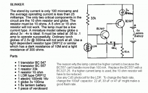
This flasher is an ancient design using a 3V lamp.  The battery is 6V, with a lot (maybe half) of the power being wasted in the 10 ohm resistor.  A LED could be used in place of the lamp, with better, brighter results.  Use a 1W LED or else use several regular 5mm LEDs in parallel.  The flasher draws very low power when it isn’t flashing, which helps save batteries.  If the right parts are chosen, it might work at 4.5V or even at 3V if red, orange, amber or yellow LEDs are used.

default

2012-12-09 Hand Cranked Light

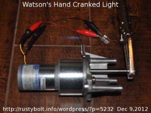
This motor and gear drive is from a mainframe computer, probably the tape drive.  The gear ratio is high, probably a dozen or more motor revs for one shaft revolution.  But that just makes cranking it turn the motor faster. The motor says it’s 30VDC, and it uses magnets.

When I turn the makeshift crank once every 6 seconds, the motor puts out about 100 milliamps to the 3V. 1 watt, 10mm white LED, making it glow brightly.  That’s about 300 milliwatts of power.  It does a good job of lighting, but it’s difficult turning the crank and holding the motor with the other hand, not to mention doing something now that both of my hands are tied up.

What would be better if it was used like this Gravity Light.  Quantsuff told me about this entrepreneur trying to develop a good version that will have a 25 pound (12 kG) weight hang from it, which supplies the power for a half hour.  If the shaft had a bobbin on it, and I could wind a length of rope around this bobbin, then hang a weight from the end of the rope, the LED would light as the rope unwinds from the bobbin.  But the distance the weight falls would determine the time the LED would light.  I guess the bobbin could be mounted high in the air, so the distance would be great.  Or else the diameter of the bobbin would have to be small, so that the  distance per revolution would be small.  Then the weight would have to be heavy.

One revolution every six seconds equals ten RPM.  If the LED was to be lit for 30 minutes, that would be 300 revolutions.  If each revolution released 4 inches of rope, then there would be 1 foot of rope for three revolutions, or 100 feet of rope unwound every thirty minutes.  That’s a bit too long for hanging this device from a limb of a tree, for example.  I can think of one easy way to halve the distance.  I could get a pulley from the hardware store and hang the weight from the pulley.  One end of the rope is connected to the bobbin of the generator and the other end is connected to the generator itself.  Then as the weight and the pulley fall, the rope would travel twice the distance, or the total distance for a hundred feet  of rope would be fifty feet of weight movement.  Of course the weight would have to be at least twice as heavy, maybe more to compensate for friction losses.

This same principle could be used with more pulleys to get less weight movement for a hundred feet of rope travel.  I don’t know how much losses there would be, but I would guess that the weight could be increased to compensate.  The power to move the weight would have to be increased too.  I’m guessing some kind of crank for the user to wind the weight back up to its highest point.

The whole point of this elaborate bobbin, rope and weight is to allow the user to store the energy so that the user can be using the energy later as electricity, thus separating the time of generation from the time of use.  Another form of  energy storage might be the same as these wind powered beach robots use in the Netherlands.  These amazing robots use the wind to pump up air stored in plastic beverage bottles, which then power the robot later.


default

2012-12-08 2 Transistor High Power “JT”

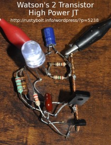
I tack soldered this two transistor “Joule Thief” V boost circuit together using one of the 100 microhenry low resistance (0.7 ohm) chokes that I bought from Mouser. I wanted a V boost circuit that put heavy current demands on the choke.

The schematic for this type of circuit is here.  I made the following changes.  Instead of 470 uH I used 100 uH.  The smaller transistor is a BC337-25 and the larger transistor is a BD433.  The capacitor is 470 pF and I replaced  the capacitor’s 1k with a jumper (0 ohms).  I changed the 2.2k to 22k and connected the upper lead directly to the +1.5V.  I changed the 1k (to +1.5V) to a 220 ohm resistor.  The LED is a 1/2 Watt, 10 mm white LED,

With the supply voltage at 1.5V, the supply current was 400 mA and the LED current was 85 milliamps (measured across the two resistors which equal 1 ohm).  The frequency was 38 kHz.  It’s capable of handling twice that much, so no strain there.  I used a half-dead AA cell to lower the light output while I took the picture – the LED is very bright on a fresh AA cell.  With 400 mA current, the AA cell is not going to last long.  It would be better to use a C or D cell, or rechargeable.

Conclusion – In this two transistor V boost circuit the 100 uH choke puts out some seriously high current to the LED.  The Mouser part number is 871-B82144A2104J.

Update Dec 10 – I removed the 470 pF cap (reddish brown blob) and temporarily replaced it with a 50 to 565 pF variable cap.  As I adjusted the capacitor, I found that the LED current fell off as I reduced the capacitance below 470 pF, and there was a broad but distinct peak at 506 pF and the current fell off as the cap increased above 506 pF.  The 470 pF that was originally used or a 510 pF are good choices.

Back to experimenting…

© RustyBolt.Info/wordpress
CyberChimps