 I watched this Youtube video where he replicates a circuit from an Instructable on designing an “Any Value Joule Thief”. I read the instructable, and found that the claims made by the author seemed far too optimistic.
The Instructable goes through multiple calculations to arrive at values for the components in the schematic. In the video, he uses a 1.2V rechargeable battery and claimed that the circuit could put out hundreds of milliamps to a high power LED.
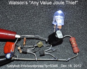
I’d like to remind you that this two transistor V booster is not a true Joule Thief. In the picture, I show my replication of the circuit. I used PN2222A NPNs for both transistors. The other components are the same values that were given in the schematic. The big resistor on the right is the 1 ohm current sensing resistor used for measuring the current through the LED. The LED was a half watt 5 chip white 10mm LED capable of handling 150 milliamps. The 100 uH choke had a DC resistance of less than 1/2 ohm.
My results were as follows. I used a supply voltage of 1.5 volts, not 1.2 volts as shown in the schematics (this should increase the LED current, giving better results). The supply current was 160 mA, the LED current was 51 mA, and the frequency was 98 kHz. At 1.2 volts supply the LED current dropped down to about 42 milliamps. This is about half the LED current of the 2 transistor “JT” circuit I blogged last week.
I thought that it might help if I removed the 100 nF capacitor which was across the Q1 (the orange blob between the clip leads). I unsoldered it and the LED current jumped up to 74 mA at 1.5V, and the supply current increased to 290 mA, and the frequency jumped up to 216 kHz. I’m not sure what the reason was for using this capacitor. The 100 nF capacitor was damping the switching and slowing down the circuit. It obviously performed better without it.
Instead of the 100 nF, I tried a 47 nF, but it still damped enough to dim the LED a bit. I then tried a 10 nF, and it dropped the frequency 40 kHz and the LED lost only 2 milliamps, from 76 to 74 mA. So a 10 nF is about the most that the circuit can handle without suffering too much.
I tried a variable capacitor across the 68 pF capacitor. But no matter what setting it was, from 5 to 140 pF, the LED current went down as the capacitance was increased. So 68 pF or less may be the optimum value.
The one thing I haven’t done is switch the output transistor. This PN2222A is capable of driving a regular 5mm white LED at full brightness. But when pressed to drive a high power LED, it cannot measure up to the task. It is quickly becoming apparent that the circuit has its limits just like others of this kind, and that no matter what calculations say, if the transistors are just average, the output to the LED will be just average. A good choice would be the transistor I used in the blog I linked to in ¶ (paragraph) 4.
Very nice explanation! Thanks for the link to my video I did indeed the similar test on my bench and the original version of this circuit is very very powerful I burn many 5 mm LED with it and yes the 100 nF cap is slowing down the frequency. I saw a version of this circuit with no cap at all I should try running LED with it to see how it perform. Cheers!