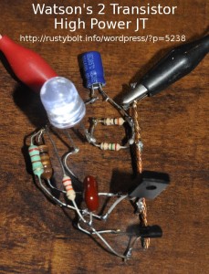
 I tack soldered this two transistor “Joule Thief” V boost circuit together using one of the 100 microhenry low resistance (0.7 ohm) chokes that I bought from Mouser. I wanted a V boost circuit that put heavy current demands on the choke.
The schematic for this type of circuit is here. I made the following changes. Instead of 470 uH I used 100 uH. The smaller transistor is a BC337-25 and the larger transistor is a BD433. The capacitor is 470 pF and I replaced the capacitor’s 1k with a jumper (0 ohms). I changed the 2.2k to 22k and connected the upper lead directly to the +1.5V. I changed the 1k (to +1.5V) to a 220 ohm resistor. The LED is a 1/2 Watt, 10 mm white LED,
With the supply voltage at 1.5V, the supply current was 400 mA and the LED current was 85 milliamps (measured across the two resistors which equal 1 ohm). The frequency was 38 kHz. It’s capable of handling twice that much, so no strain there. I used a half-dead AA cell to lower the light output while I took the picture – the LED is very bright on a fresh AA cell. With 400 mA current, the AA cell is not going to last long. It would be better to use a C or D cell, or rechargeable.
Conclusion – In this two transistor V boost circuit the 100 uH choke puts out some seriously high current to the LED. The Mouser part number is 871-B82144A2104J.
Update Dec 10 – I removed the 470 pF cap (reddish brown blob) and temporarily replaced it with a 50 to 565 pF variable cap. As I adjusted the capacitor, I found that the LED current fell off as I reduced the capacitance below 470 pF, and there was a broad but distinct peak at 506 pF and the current fell off as the cap increased above 506 pF. The 470 pF that was originally used or a 510 pF are good choices.
Back to experimenting…