default

2012-12-07 LED Current Controller

I was reading a forum which showed a picture one contributor added.  The schematic of a circuit consisted of one opamp of an LM324, its output feeding the base of a transistor and the – input connected to the emitter.  The transistor had its emitter connected to ground through a 1 ohm resistor.  The collector was connected to the cathode (flat spot) of the LED, and the other LED lead was connected to +5v.  The LM324 power pins went to +5v and ground.  The + pin of the opamp was labeled “1 mA / mV”.

Assuming that the LED is a regular 5mm and needs 20 mA, the +pin then must be supplied with 20 mV.  That’s not so easy to do.  For a 5V supply, that means a two resistor V divider must be added, with values of 250k for the upper and 1k for the lower resistor.  It would have been better if the 1 ohm resistor was 100 ohms and the input was labeled “10 mA / V”, so 2 volts would then be needed at the input.

But if the LED current does not need to be changed, and is a constant 20 mA, then this circuit is a waste of the opamp.  A simple two transistor current regulator would do just as well.

But if the supply voltage is relatively stable, then just a fixed value resistor would be just as good.

default

2012-12-06 Gravity Light

Years ago I became acquainted with one of our librarians, who was from Germany.  He told me he lived in Dresden during World War 2, and he had a flashlight that had a handle which he could squeeze and it would light the bulb.  But he said he lost it and everything else when the Allies firebombed Dresden and the city burned.

My point about relating this story is that the idea of using human energy to power a light is not new.  For many decades, the electric generators have been using human and animal muscle to convert sweat into electricity.

This time. a few inventors have developed the Gravity Light.  This device uses a weight that is periodically lifted to store enough energy to power the light for tens of minutes.  In their video, they do not show the actual unit in operation, but I assume that it uses a series of gears to turn the very slow moving weight’s downward travel into a much higher speed of rotation of the generator’s rotor.  This was essentially what the hand powered light did, except it had to be squeezed constantly to keep the light lit.  But instead it requires the user to lift the weight up, and over time this weight slowly drops as it powers the generator.

When you think about it, you will realize that this is the same thing that the hydroelectric power stations do at the dam at the reservoir.  The generating station converts the falling water to electricity, by using it to turn a turbine, which turns the generator.  The water must fall from a high to a lower place in order to release the energy.

The website said that the first production run of the Gravity Lights won’t be available until March, 2013.  People don’t realize what a health hazard fires are, whether from cooking or from a kerosene lantern.   I think this product would make a good investment.  If the price could be kept low, it would be usable in many more places than the solar lights, because it doesn’t depend on sunlight.

Thanks to Quantsuff for sending me the link to this project.  Check out some more LED projects on his website.

Update Dec 12 – Mark commented:

Such a clever idea, seems incredible that clocks have used this principle since the 17th century and yet no one thought of this before.

Clocks have used this weight system for power for centuries, but they thought up a better way to power electrical appliances long ago. They had the rotating wheel, just like this Gravity Light has, connected with gears to a generator, just like this Gravity Light.  And they added some weight, just like this Gravity Light, in the  form of water.  They put some buckets, just like this Gravity Light has, on the wheel, and BINGO!  They had a water wheel, capable of generating enough electricity for a small village.

The company has surpassed their $55,000 goal by a sizeable amount.  You can read more about it here.

default

2012-12-05 Linverter DC to DC Converter

About March, 2004 I ordered a kit from eBay IIRC, from a guy in another country, might have been Britain.  He called it a Linverter.  At that time I didn’t have that much experience with DC to DC converters.  I assembled it, made some modifications to it and learned more about how to get the performance required to drive LEDs to full brightness from a 1.5 volt AA cell.

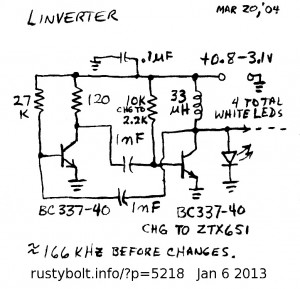
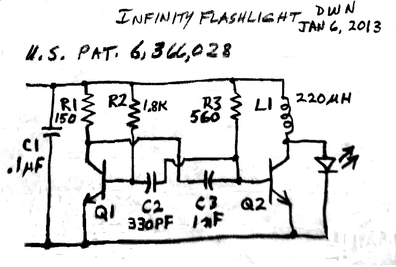
IMG_20130831_163448The schematic shows what at first looks like a two transistor “”Joule Thief” type V booster, but it’s not.  It’s an astable multivibrator with one collector load resistor replaced by a 33 uH choke.  The circuit runs fairly fast – 166 kHz – and does a good job of driving four white LEDs.  However I don’t think the 120 ohm resistor needs to be that low.  I think it could be increased to 220 ohms or more without much penalty in performance.  That would save some battery current.  I changed the output transistor to a high current one, but the BC337-40 does a good job of putting out current and it’s much easier to obtain than the one I used.  If I needed more current I would just put a second BC337-40 in parallel with the output, but give it its own choke and add the LEDs to it, like the original.  This circuit looks similar to the one that CMG patented for their Infinity LED flashlight. I have included the schematic here.

default

2012-12-04 Solderless Joule Thief Uses Air Core Coil

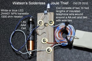
I took this photo just before Halloween back in 2010, after I made this Joule Thief without solder and without a toroid.  It shows that you don’t have to know how to solder and you don’t have to have a toroid to make a working Joule Thief – all you need is a screwdriver.  So do your thing and experiment a bit, and see what you can come up with.

Each screw (except for one) has two washers to hold the wires.  Putting two or more wires under the screw head without the washers will be difficult and the wires will try to come loose.  Two or three washers makes it easier and the wires are held much firmer.  The wood block is a piece of solid oak that is about a half inch (12mm) thick.  The oak is very hard and the screw holes have to be drilled out before the screws are put in.  This also makes it possible to use small screws with a flat end which were used for holding plastic parts together.  The screw size is about #3 by 3/8 inch long, with coarse threads like a sheet metal screw.

The LED is not very bright because it’s a cheap 3 mm white LED I got from an eBay seller, and it has been used a bit so it has dimmed.  Use a decent LED and this circuit will be as bright as a toroid JT.

DSCN1224S3Another Joule Thief I put together is shown in the second photo.  This uses the bare wires to wrap around the joints in place of solder.  The joints are not as mechanically strong as solder but for a quick experiment they should work okay.  If the JT is going to be used, the wire joints may become intermittent or loose.  The solder joints are a much better connection.

default

2012-12-03 Super Sensitive Whisper Detector

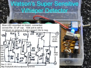
I built this circuit back in June 2010, but it wasn’t stable, and tended to motorboat (yeah, the output went putt-putt).  I had to do some troubleshooting to find out what it needed to cure the problems.  I finally got it running, and was I in for a surprise!  This thing is super sensitive, it easily detects a whisper at 12 feet (4 meters) away.  But it has to be in a very quiet area, or else the blue LED just stays lit from all of  the ambient noise.  As it is, I had to turn the TV off down the hall in the living room, because it just sat there and blinked with every barely audible sound from the TV more than 25 feet away.

I originally put the 100k adjustment pot to adjust the turn on threshold, but it has so much gain that the I set the adjustment pot to minimum and it still lights up really brightly.  So all I have to do is ground the 33k resistor end that goes to the pot.  The 100k pot could instead be used for a sensitivity or volume control by putting it between the stages where it says ‘not used’ on the schematic. [There was a 12 hour pause during which something went wrong in the website…]

The BC550C NPN transistors are high gain, low noise for audio preamplifier use, but the ubiquitous 2N3904 should work instead.  The BC337 supplies vey little current so it coule be replaced by any NPN, such as the 2N3904.  The BC327 has to supply a very high peak current to light the LED, so it should be a high current PNP transistor.  I would use a PN2907A, 2N4403 or similar.  Others such as the 2N3906 or BC557 will sacrifice brightness, but the rechargeable batteries will not be discharged so fast.  But this detector should be very bright and colorful, so put a few more different colored LEDs in there.  Some of the lower voltage LEDs such as the red or orange may require a resistor in series to prevent current hogging.

I brought this to work.  At home it works very well, with a quiet evironment.  But at work with the ambient noise from air conditioning, equipment, and people, the blue LED tries to stay on most of the time.  I can go into a small room or storage room and the noise is low enough to let the LED go out.  Then it detects the whispers easily from several yards away.  But the other places are mostly too noisy to allow the LED to go out.  And I didn’t give it a volume control, so I can’t reduce the sensitivity and the LED lights up steadily.

Back to experimenting…

default

2012-12-02 Blue Blinkies for Xmas

I wrote this article last year about my Blue Blinkies.  I have rounded many of them up and I tied them under the eaves of my house as a substitute for Xmas lights.  But I ran out, and had to use a bunch of other LED blinkies.  So yesterday I called up my old ExpressPCB layout of the original batch of PC boards I had made.  I ordered another fifteen of the boards and they should be arriving by the end of next Tuesday.  I then have to cut them up and stuff them with the parts, so I can complete the decoration of my garage, which needs about 8 or 10 more.  Looks like I can already get on the job of rounding up all of the transistors, resistors, capacitors, etc to complete the boards.  I’m pretty sure I have enough transistors, since I bought hundreds a while back.  But I may run short of resistors and capacitors.  I need to make a BOM (bill of materials) so I can pull out a package of parts from my parts drawers.  Oh it’s so much fun…

Back to experimenting…

default

2012-12-01 Free Energy!!!

This is for all those free Energy fanatics who claim they can light over a hundred LED xmas lights to ‘full brightness’ on a single AA cell.

I put four white LEDs on a small PC board in series, and connected them to a 9VDC wall wart AC adapter, which put out about 15 volts open circuit.  Each LED dropped about 3.2 volts, so the total drop added up to 12.8 volts.  I put an 82 0hm current limiting resistor in the wire coming out of the inline jack and taped it up with electrical tape.  The current, calculated from the voltagedrop across the 82 ohm resistor, was 16 mA.  The adapter has no regulation so as the line voltage changed, I saw the current change.

As can be seen from the photos, the LEDs took several minutes to dim after the adapter was unplugged.  Free energy!  Coming out of nowhere!  So I lied.  The glow is from the energy stored in the electrolytics inside of the adapter.

default

2012-11-27 Says TN0702 “Not Good Enough”

The Youtuber going by the name of Sanjev21 has read my comment about using the TN0702 low gate threshold MOSFET for a Joule Thief that will start and run below 0.6V.  He replied that this has a Rds(on)of 4 ohms at 2 volts, which is “too high”. The problem is that he is using a regular junction transistor that will not start at voltages below 0.4V, which makes it necessary to use a pushbutton to get it running at very low voltages.   Using a pushbtton or anything that requires human intervention to get it running is unacceptable in my opinion; it should start by itself.

Think Outside Of The Box

This Youtuber has too narrow minded to think outside of the box.  I can get the circuit to start and run at very low voltages and I don’t even need a transistor to do it.  It involves using technology that is way over a hundred years old, invented by a painter and used extensively by the railroads back then.  It was also used back in the early days of car radios to boost 6V to hundreds of volts.  Another hint is that it can be very noisy when it is running.

Very Low Voltage Means Very High Current

Remember that when a circuit has to operate at very low voltages, it puts very high demands on the circuit; the resistance of even a short piece of wire can be detrimental.  Circuit board traces must be very heavy to accommodate the very high currents.  The current passing through the transistors may be hundreds of times higher than in a simple Joule Thief.  So it’s difficult to get high performance from these circuits.

But back to the TN0702.  In my blog I gave some figures on how well this MOSFET did in a JT circuit.  It does better than the junction transistors I used – and I used some very high current transistors.  Also two or more of them can be put in parallel to reduce the on resistance and get more current to light the LED.  Or this circuit can be used to boost the voltage up high enough to drive the gate of a very high conductance MOSFET such as the IRL3302 .  More about this in my blog here.  The MOSFETs are capable of handling many times more current than junction transistors.  Also, they take less gate current than junction transistors.  A 2N3055 for example, might have a current gain of only 30 at 15 amps, its maximum current.  That means the base must be driven by more than a half amp – 1.5 amps or so – to get the 2N3055 to go into saturation.  The MOSFET gate capacitance needs to be driven but not at such high currents.  And the MOSFET can handle much more than 15 amps.

Back to experimenting…

default

2012-11-24 LED Xmas Light Review & Teardown

QS sent me a link to a series of Youtube videos of xmas LED light reviews.  This review is on my mind right now.  It’s a review and teardown of a 15 RGB LED light string from Brite Star. This is in my opinion an excessively long video at 55 minutes.  I think it would have been better if he gave the synopsis at the beginning and then advised the viewer that he could skip the technical details.  Or else he could have broken it up into more than one video.  For those pressed for time, they can skip to the 50 minute point and get a synopsis.  We’re all pressed for time, what with family, work and time spent on day-to-day necessities, so it’s hard to justify  spending a whole hour of one’s time watching a review of a single product.

For a xmas LED light string it’s quite complicated.  He opens up and shows the ‘photocoupler’ (their term for optocisolator) and controller.  At 23 minutes it gets more interesting as he tears down the controller and comments on the design of the packaging.  This light string uses a COB (chip on board) on the controller, the photocoupler and each LED light – which to me adds a lot to the complexity.

Fortunately all of this is assembled with screws so it could be repairable and hackable by those so inclined.  From what I saw, the photocoupler allows a series of strings to be daisychained together, and the photocoupler allows one controller, presumably the first in the line, to control the whole string.  To me, this photocoupler opens up a lot of possibilities.  If the signals coming out of it are not unique to this light and are standard enough to be readable by other devices, then it could be connected to an external system and be used to control other things.  Or looking at it the other way, if the strings accept data that is a standard format, then other devices could be used to control the strings.

It’s kind of surprising how many microcontrollers have popped up in all sorts of places, such as appliances, equipment, and portable devices.  Another thing that has happened without most people knowing it is the number of microcontrollers that are used in vehicles.

Aside – In the video I saw his Fluke 87 V DMM, and later googled it.  I came across this web page where you can buy one for a hundred million dollars!!!  Well, maybe it’s actually cheaper than that.

Back to experimenting…

default

2012-11-23 Xmas Tree Light Time – Blue Blinkies In The Eaves

I put up xmas lights in the eaves.  Most of them were Watson’s Blue Blinkies.  I also put up some of those pigeonsnest.co.uk flashers that I built years ago.  I think some of them have been flashing for a year on the same cell, so long that I figured it was a lot cheaper to just solder the supply leads directly to the AA cell.

I got a couple dozen AA alkaline cells from Fry’s at a deep discount, and they should last at least a year.  I can probably put them away after the season and use ’em again if they don’t leak and go bad.   I’m hanging them from the rafters, behind the fascia board, so they won’t get rained on.  I didn’t realize how many of these I would need – there are a lot of eaves!  I need some more for the garage.  I’m thinking of putting some of the PSO fading LEDs there.  But they won’t run long off batteries.  I was thinking of putting a solar panel out to charge a bank of 2600 Farad ultracapacitors, which should last most of the dark hours.

I went to Home Depot in search of the Philips L Prize LED lights.  I came away emptyhanded but I did get some other stuff, including some cheap LED xmas light strings.  Now I have to modify them to make them go on and off so there will be less power consumption.  More on this soon.

Update early December – I ordered another batch of 3 MiniBoards from ExpressPCB, with each board laid out with five of the Blue Blinky boards.  I got them, sawed them apart, and stuffed them with the parts and soldered them up.  I used various colors of LEDs, and fired them up.  On these I added the red LED as the light sensing diode, so all of them will shut down during the daylight hours.  I outfitted them with the batteries and wires, and hung them from under the eaves, each one hung from a small nail in each of the boards.  They’re back a few inches so the rain doesn’t get them wet.  Tonight, Dec 19 and tomorrow morning the temp outside is supposed to fall into the high 30’s, so it will be a good test to see if these hold up in the cold.  That may not seem to be very cold to some folks, but for So. Calif, it’s about as cold as it gets.  It seldom freezes here, and only occasionally gets below the high 40’s during the winter.  Hey, it’s a temperate climate with a temperature that is kept quite stable by the Pacific Ocean when the wind is from offshore.  But tonight it’s going to be BRRRR!

© RustyBolt.Info/wordpress
CyberChimps