default

2012-12-31 Pulse Generator Circuit

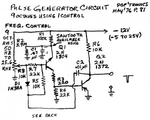
This schematic is from an old 1976 magazine.  It uses germanium transistors, but the circuit looks to me like more common silicon transistors could be used instead.  It uses a negative 12V supply, but I would use a positive supply, change the transistors, reverse the diode and use a non-polarized capacitor in place of the 0.47 uF electrolytic.

This circuit looks very similar to the two transistor “Joule Thief” type circuits that we often see on the ‘net.  An NPN feeding into a PNP, and the C2 feedback capacitor to make it oscillate.  The collector load resistors are 100k and 10k,  At 12V, more than a milliamp could flow through R6, but since that transistor is off most of the time, the average current is much lower.  In contrast, the 555 would use many milliamps current.

For pulses at audio frequencies, the circuit could probably use a few resistance changes.  The reason is that germanium transistors have lower current gain and higher leakage than silicon transistors.  I think that R8, R7, R5 R4 could all be increased.  And if that is done, C2 may be decreased to keep the frequencies within the audio band.

Also, the output across R10 is medium to high impedance, so I would put another transistor after this as an emitter follower to decrease the output impedance and increase the output current.  The transistor might have a 1k to 2.2k emitter load resistor, with its other end connected to the supply and its collector connected to ground.  Connecting it this way would minimize the supply current since the voltage across R10 is very low most of the time.

I mentioned the 555, because this circuit could be used as a substitute for the 555 as a very wide range pulse generator.  The circuit has no adjustment for the pulse width, but a variable resistor might be added to vary the pulse width somewhat.  This resistor might go in series with C2.

BTW, with the negative supply as shown, the pulse is shown as negative going.  But actually it would be the opposite, with the output at -12V most of the time, and during the pulse’s peak, it would be approaching zero volts.

default

2012-12-30 Light Deactivated Alarm

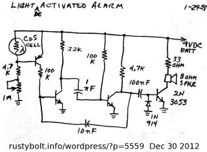
This light deactivated alarm (or should it be called a dark activated alarm?) might be used as a detector when a light beam is broken.  I would use a red LED and restrict the light to a narrow beam so that it would be hard to see.  When the CdS cell is illuminated and the circuit is deactivated the current drawn is only a few tens of microamps depending on where the 1 meg pot is set.

The two middle transistors are basically an astable multivibrator, with the 100k base bias resistor of the left transistor going to the collector of the PNP transistor, which acts as a switch to turn  it on when the photocell is unlit.  The right transistor is driven through the 100nF and directly drives the 9 ohm speaker.  This transistor has no base bisa; it is running as a switch so it should not get hot.  The 33 ohm resistor in series with the speaker limits the current through the speaker so that it doesn’t sound too loud and so it doesn’t overheat.

I once built a similar circuit using a small 1.5 inch speaker rated at about 0.2 watts.  After a short time, the speaker voice coil went open, probably from excessive current and temperature.  So if you decide to leave out the 33 ohm resistor, you should consider using a speaker capable of handling much more than 0.2 watts.  Also, the 2N3053 is expensive and not easily obtained.  I would suggest using a BD135 and small heatsink if it gets hot.

default

2012-12-29 Important Construction Practices for Joule Thief

I found that my modified Joule Thief circuits were running at the frequency of 550 kHz, or at the bottom of the AM broadcast band.  This is the highest frequency that I have settled on as a satisfactory frequency for a Joule Thief.  I have built ones that have gone as high as a few MHz, but they were just to see how high the JT could go and still function.

What is important is that when the frequency gets above a few hundred kHz, then the circuit becomes more dependent on the stray resistances, capacitances and inductances of the wiring and PC board traces.

People often assemble a JT on a proto board or with clip leads.  The stray capacitance between the contacts inside of the board will cause the circuit to have a different operation than if it was tack soldered together.  And using the clip leads to assemble the circuit adds an excessive amount of stray capacitance and inductance so that at the higher frequencies, the circuit may become unstable so that it operates erratically or quits altogether when the clip leads are moved.  The proto board also has more stray capacitance than a PC board, and the circuit may work differently than if it is on a PC board or tack soldered together.

The most damaging of these to a Joule Thief is the stray resistance.  The voltage is so low that any stray resistance becomes much more detrimental to the circuit.  When a circuit is running at 12 volts, a small resistance might be tolerated.  But when a circuit is operating at 1.2 volts, that same small resistance becomes ten times more influential on the circuit and ten times more detrimental – it can ruin the performance.  The solder joint is a very low resistance connection; the contact in a proto board and the clip lead are not low, their resistance affects the circuit much more.  And this is especially true if the proto board’s contacts are old and dirty.

Some circuits (not the conventional JT) require a tuned circuit with a capacitor and inductor in parallel.  These two components have a very high circulating current when they are working properly.  The hams would use silver plating to reduce the resistance and increase the Q or quality factor.  Using a proto board to hold the cap and coil adds resistance to the circuit, which reduces the Q or quality factor, and this makes the tuned circuit’s performance lower than if the cap and coil were soldered together.  The penalty is even greater with clip leads (see  note below).

If the experimenter is going to build any circuit where the frequencies are more than a few hundred kilohertz, then he or she should learn how to use good RF construction practices.  Keep leads short.  Make good mechanical connections to the leads before soldering.  Make good solder joints.  And use good quality components for the critical circuits where RF is highest.

One can download this 256 page manual on RF and microwave grounding.

Note: I bought a hundred mini alligator clips online, in red and black.  I made my own clip leads with wire that is only four inches or 100mm long, so the clip leads have a minimum impact on the circuit.  They are supposed to be temporary, and not the way to build something.  If you want to hold leads together, you should buy a hundred Fahnestock clips to hold the component leads together with no extra wire.  At least they don’t have so much capacitance as the proto boards have.

default

2012-12-27 My Second Modified Joule Thief & 3rd

I my previous blog I determined that the Joule Thief flasher was not suitable as a flasher, but it was working well as a modified Joule Thief, with better efficiency than a conventional JT.  I gave the schematic of the circuit, but I have made many modifications, so I decided to build a second one so that I can get another separate and independent idea of what this circuit can do.

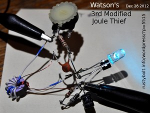
I tack soldered the circuit together so I could take a photo of it and show how it was wired.  It’s a simple circuit, not much more complicated than a conventional JT, with the exception of a capacitor added in series with the feedback winding.

The circuit is the same as the original, a PN2222A with a base bias resistor of 3.9k and the capacitor is 100 pF.  The coil consists of a Fair-Rite 26730042402 core with 16 inches of 28 AWG trifilar wound on it.  Two of the windings are connected in parallel for the primary winding.  The inductance measured 750 microhenrys.  The LED is a white LED, and the green thing below it is just holds the 1 ohm current sensing resistor and makes it easy to connect to it.

I connected a variable capacitor to the circuit and adjusted it for maximum LED current.  I removed it and it measured 96 pF, which was so close that I replaced it with a 100 pF disk capacitor.

Results

For my second circuit, the supply current at 1.5V measured 95 milliamps and the frequency was 410 kHz.  The LED current measured 16.1 milliamps.  The LED current was close to the original but the supply current was almost twice that of the original.  This was much less efficient than the original.  But the original used a coil with 262 uH, and this coil is nearly three times that much: 750 uH.  This may be the reason why the efficiency is lower.  I would say most of the difference in the circuit is in the coil, since the rest of the circuit is about the same.  I may remove some turns from the coil to see if it helps increase the efficiency.

Big Change For The Better With Fewer Turns

I removed 6 inches of wire, leaving about 10 inches.  Each winding measured 263 microhenrys.  I reconnected the windings and fired it up.  To my pleasant surprise, the LED current remained at 16 milliamps but the supply current had gone down, to a bit below 50 milliamps.  The frequency was 494 kHz, near the first’s frequency.

So now this second modified Joule Thief was giving me the same efficiency as the first one, and slightly more LED current with about the same supply current.  The capacitor was still 100 pF.  At 494 kHz, the reactance of this capacitor is about 3222 ohms.

The 16.1 mA LED current is at the bottom end of what I would like it to be, which is 20 mA.  I decreased the resistance from 3.9k to 3.3k, and the LED current went up to 17.8 mA, which is a very comfortable value, almost 20 mA, and it has nearly the same light output.  The frequency then went up to 550 kHz, right at the bottom of the AM broadcast band.  But to keep everything at the same point, I changed the resistance back to 3.9k so that any further changes would be relative to both the first one and this modified JT.

A Third Modified JT

Just to confirm what I’ve done before is not a fluke, I built a third modified JT.  This one used the same Fair-Rite 2673002402 core but the turns were less, just enough to give a bit more than 100 uH.  Both windings were 8 turns, one winding of 24 AWG telephone wire (white/blue) and the feedback winding was 30 AWG enameled magnet wire.

I used a PN2222A again and the LED was a blue-green with a voltage drop of about 2.9 volts.  To make up for the difference between 2.9V and the usual 3.2 volts of the typical white LED, I put two resistors in series with the LED to ground, one resistor was 10 ohms so I could measure the current.  I found that these resistors caused the LED to be dimmer, so I put a 47 uF capacitor across them to allow the peak current pulses to flow unimpeded through the LED.

I put a 10k pot in series with a 1k resistor so I could adjust the amount of base bias current.  As previously. I put a variable capacitor in place of the ceramic disk, and adjusted it until I got a broad peak,  It measured 112 pF, so I again removed it and used a 100 pF ceramic disk capacitor.

The performance is very close to the other two.  With the pot adjusted for 50 mA supply current at 1.5V, I got 15.6 milliamps LED current, and the frequency was 556 kHz.  The performance was very similar to the two previous modified JTs and the efficiency calculated to about 68 percent.

I’m satisfied that the circuit is easily replicated and the performance is consistent with the same part values.

default

2012-12-26 Lossev’s Crystal Oscillator Experiments

I was looking through the Yahoo group lost_technology and came across an article from the Wireless World, 1923 about the Russian O. Lossev’s experiments with crystals (the mineral kind like those used in detectors).  He got best results with zincite and a carbon or steel whisker.  I have a galena crystal, but he got poor or no results with it and others.  So I decided to look for some zincite crystals for sale online.

I came across some for sale for anywhere from a couple hundred dollars (US) to thousands of dollars.  Apparently fine zincite crystals are very rare and hard to come by, most being from Poland.  Of course you can grow your own zincite crystals, but then you have to have all of the paraphernalia that is needed to do that chemistry stuff.

While searching for some cheaper (much cheaper) ones, I came across a website that had all sorts of eclectic stuff, like one commenter said anything from trash to treasure.  The seller didn’t have any zincite mineral, but there was a lot of other interesting stuff, some quite out of the ordinary.

I continued to read the article, and found that the zincite may have to be purified by fusing it in a carbon arc along with manganese dioxide.  It also recommended using a certain kind of detector for holding and probing the crystal with the whisker.  This was getting a bit more complicated than I thought, and I decided that between the high cost and unobtainium of the zincite and the rest of the paraphernalia, I may just stick to using some tunnel diodes that I have in my parts drawer.

Back to experimenting…

default

2012-12-25 One Transistor Radio Improvement Mods

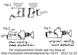
This photo was posted to the files section of the Yahoo group lost_technology.  I’m including it here so others don’t have to sign up or log on to see the photo.

Since this was from a group for antique stuff, we will assume that this radio circuit is very old and uses Germanium transistors.  The 1N34 germanium diode is very old technology and helps us date the circuit.

In fig.2 the author shows how to ‘improve’ the original circuit shown in Fig.3.  In Fig.3 there was no base bias current, which in a germanium transistor isn’t so bad because they are somewhat leaky, but still this caused distortion.  In Fig.2 the base bias is added by the 100k resistor.

In Fig.2, the 2 uF capacitor is much too large a value; it can be 0.1 uF or even less since it is passing RF (radio frequencies).  The problem is that since the 1N34 diode is in series with the base, the RF is passing through the 1N34 and right into the transistor’s base, so the transistor is also amplifying RF.  It should only be amplifying the audio frequencies for the speaker.  There should be a RF bypass capacitor from the base to the emitter, about 0.01 uF or so, enough to bypass the RF and leave the audio.   There should also be bypass capacitors from the collector to the emitter, and across the battery, so RF doesn’t have to go through the audio section.

But an important point that I would like to make is that in Fig.2, the 1N34 is in series with the base, so they are both detecting or rectifying the RF, so if the 1N34 was replaced with a jumper, the base would detect or rectify the RF.  In other words, the 1N34 really is just duplicating what the transistor already does and really isn’t needed.  And if there were bypass capacitors across the transistor, then the RF would be filtered out and only the audio would then get to the speaker.

Merry Christmas, and happy holidays.

default

2012-12-23 Watson’s Massively Parallel Capacitor Array

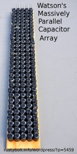
I finished gluing the 10 000 uF capacitors down to a piece of wood.  I now have a Massively Parallel Capacitor Array (MPCA)  Now the hard part comes: connecting all 150 of them up in parallel.

I bought a whole box of 250 electrolytic capacitors on tape and fan folded.  They were only ten dollars US from Goldmine-Elec.com.  I sure wasn’t going to be able to use all of them up in various projects in my lifetime, so I had to have something to use most of them up.  I got a piece of 3/8 inch plywood 4 inches wide by 24 inches long, and marked some rows out in pencil so I knew where the caps were to be placed.  Most of the day and a tube of silicone seal later, I had them in place and ready to dry overnight – see the photo.

Now the hard part comes: connecting them together with some heavier gauge wire.  I think bare wire would be easier to work with.  I’m still wondering about overcurrent protection.  Should I put a fuse on each long row, or will a single fuse for the whole array be sufficient?  How much current should the fuse handle?  This array adds up to a lot of capacitance, a total of 1.5 farads.  And at ten volts, that could be a lot of current if it was shorted.  I don’t plan on charging it quickly; maybe over the day with a solar cell.  Then get it to light LEDs at night.  But I got to figure out how I want the array energy to be converted and used.  Should I just use analog parts, like regulator chips?  Or should I treat it like a variable voltage source, and let a buck-boost DC-DC converter change the array’s output to a fixed voltage?

Lots of questions that I need to investigate and answer.  I have a bunch of Maxwell 2600 Farad, 2.5 volt ultracapacitors, and those have so much energy that I can treat them like a voltage source and just connect a Joule Thief to them and run the LEDs from that.  I also bought some DC-DC converters on eBay, each is capable of taking in unregulated voltages and putting out a steady voltage.  They’re very efficient and barely get warm.  I may be able to use one of these on the MPCA to stabilize its output.

I started out with a box of 250 caps, on fan folded tape.  Now, after using up 150 on the MPCA, I still have nearly 100 caps left.  If I had a smaller piece of wood, I could wire up more of them – maybe 50 more – in another array.  Then I could bring the total to 2 Farads.  Maybe I’ll get to that later.

Update – The weekend before New Years Eve – I took apart some multiconductor foil shielded cable and salvaged the bare stranded wire from it.  I think it was about 22 AWG, and I used it all up – about ten feet – to wire up the MPCA.  I still wasn’t finished so I had to strip off some other wire to get more bare stranded wire to finish.  Now that all the hard work is done and I have all of them wired up, all I have to do is mount a terminal strip on the MPCA board and wire them all to the terminal strip.  Wow.  I can’t believe it’s nearly done.  When I started, I thought it was going to be a daunting task.  It took time and patience, but nothing that posed a technological challenge.

Back to working on the MPCA…

default

2012-12-20 Scheduled Power Loss For More Than An Hour

Last week I got a postcard from So Cal Edison telling me that there would be a scheduled power outage on Dec 20 from 9 AM to 3 PM.  Well this morning I was working on the PC and sure enough, about 10:30 the lights went out.  Since it’s a laptop, I didn’t lose anything.  But my DSL modem was off of course.

It’s not funny when you go to do something and it doesn’t work because there’s no electricity.  Like I turned on the stove burner and the ignitor didn’t work because there was no power.  So I had to bring out the barbecue lighter and light the gas manually.  Sheesh!  I hope the gas water heater isn’t the same way.  Luckily it has enough hot water to hold over for a few hours.  Maybe the Maya Calendar was right!

I decided to go for a walk, and ended up in a thrift shop where the lady had a Meade astronomical telescope with all the eyepieces and other stuff for $100.00, which is considerably less than what it cost originally.  I think it had a four inch lens – it’s a refractor.  I aimed it out the window and saw stuff more than a block away as if it was right outside the door.  I may go back and buy it if it’s still there.

I got a sub sandwich and came back after 1 PM and the lights were back on,  My problem was the DSL didn’t link up for what seemed like hours.  Finally I could get back online, but everything seemed slower, I think because the cookies that I had built up were gone and every site had to meddle with my PC to get it to where it was before, so it could trust it again.  Like, “You don’t look familiar.  Let me double check to see if you’re on my list of acceptable users.”

Anyway, now that I’m back online, I’ll have to catch up on what I was planning on doing before this morning.  My next blog should be an  indication,  But first I gotta go around to all the appliances like the microwave oven and reset the time so the display doesn’t blink all the time.

default

2012-12-22 Joule Thief No Good For Flasher

Update: This circuit is much like the Supercharged JT, see the end.

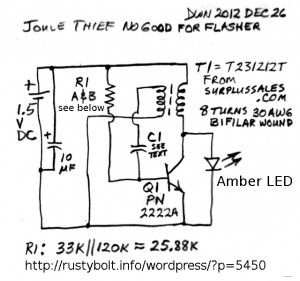
A while back I built a Joule Thief flasher, like the one I had seen somewhere on the web, most likely on Youtube.  The schematic shows the different arrangement of the feedback winding and base bias resistor.  Normally the feedback winding is in series with the 1k resistor to the positive supply.  But in this arrangement, one lead of the feedback winding is connected to negative, and the other lead is connected to the timing capacitor.  In my first build, I had used a 120k ohm resistor for the base bias from positive to the base, and a 33 uF ‘lytic for the timing capacitor, but the flashes were so fast that I had to put another 220 uF capacitor across the 33 uF.  Even with this large capacitor, the flash rate was still too fast.  And the flash was very weak, not really visible.  The supply current was very low, only a milliamp or less.

So at this time, I decided that if I was going to use an even bigger timing capacitor, I would have to use a smaller timing resistor to give the transistor more base bias and help brighten the LED (I used an amber LED).  I put a 33k resistor across the 120k, which was then effectively 25.8 k.  The flash rate sped up, but the LED didn’t get much brighter.  And at this time, I figured that if I lowered the timing resistor down to where the flash was much brighter, the timing capacitor would have to be a thousand microfarads or more.  Nix to that!  My Supercharged Joule Thief Flasher does a much better job with a capacitor of a few uF.

So now what should I do?  I’ll change it back to a Joule Thief, but I will just leave it like it is, with the feedback winding to negative.  So I removed the capacitor and put a 0.1 uF capacitor in its place.  Well, of course the flash rate sped up so fast that the LED looked continuously on to my eye.  But it was still too dim.  The frequency was 4567 kHz.

I removed the 0.1 uF capacitor and put a .01 uF capacitor in its place.  The LED was brighter and the narrow pulses were getting closer together, as I saw them on my ‘scope.  With the scope on the collector, the waveform was a narrow low positive voltage spike, followed by a much more negative voltage spike.   The frequency was 46 kHz, but there was still a lot of ‘dead time’ between spikes.  I figured that if I decreased the timing capacitor even further, the spikes would get even closer together and less dead time would mean a brighter LED.  So I replaced the .01 uF with a .001 uF or 1 nF.  The LED became brighter and the spikes were closer together.

Well, I figured that the spikes needed to be a bit closer, so I changed the timing capacitor to a 330 pF.  Now the LED was getting bright enough to see decently and the pulses were close together.  The frequency was 172 kHz.   Even so, the supply current was only 5 mA, which is less than a tenth of a normal Joule Thief.

Conclusion

Right now, I can say from this experience that this circuit the way it is, is not the optimum for a Joule Thief, and that it is definitely no good for a flasher, even though the circuit does flash dimly.  I will try to increase the base bias current by reducing the value of the resistor below 33k in parallel with 120k.

I have changed R1 to a 5.6k resistor, which was the value that gave about 50 milliamps supply current.  The amber LED brightened considerably.  I put a 0.47 ohm resistor in series with the LED so I could measure the LED current.  The LED current was maxed at 15.5 milliamps when I changed the capacitor to a variable capacitor and tuned it to 101 pF.  So I replaced it with a 100 pF disk capacitor. The frequency was almost 300 kHz and the supply current at 1.5V was about 50 milliamps.  That was very low for a current of 25.5 mA through the amber LED.

The amber LED was brightest when the variable capacitor was broadly tuned to a certain point.  This is much like the Supercharged Joule Thief, where the capacitor interacts with the coil’s feedback winding to give higher efficiency than a conventional Joule Thief.

I removed the amber LED and replaced it with a white LED.  This is so I can make an “apples to apples”comparison with the Supercharged JT.  I further reduced the R1 to 3.9k, to increase the supply current up to the point where the Supercharged JT usually is.  I was getting about 15 mA to the LED with a supply current of 48 mA.  The frequency was 593kHz which is very high, at the bottom of the AM broadcast band.  Some figures for calculating the efficiency:

3.3V * 0.015A = .0495 W or 49.5 milliwatts.

1.5V * .048A = .072W or 72 milliwatts.

49.5 / 72 = 68.75 percent.

So this circuit is on the very high end of efficiency of the conventional JT, but on the low end of the efficiency of the Supercharged JT.  I will have to make another one or two of these to see if the circuit is consistent with the parts I used.

I’m building a second one, so read my blog about it here.

Back to experimenting…

default

2012-12-19 Power Save Joule Thief With C9011

I received a google alert with this Youtube video of a Joule Thief which uses a C9011 transistor.  The notes give a link to the data sheet for this transistor.  The actual designation for this transistor is C9011, not 2SC9011 (see note at end).  As can be seen in the data sheet, the transistor’s absolute maximum collector current is only 40 mA.  Also, the Pc is only 400 mW – most transistors can dissipate 625 mW or more.  Notice that it says it is meant to be used as a converter and IF amplifier.  To me, this means that to get lower capacitance and better RF performance, the makers made the chip and junctions smaller than the typical transistor to reduce Cob for example.  That’s another reason why the current and power are lower.

The typical Joule Thief needs over a hundred milliamps from the battery to give the typical white LED the 20 milliamps that gives true “full brightness”.  This C9011 should not be made to go past 40 mA collector current, but it probably is, and very reluctantly.  It just can’t do it because the transistor is too small, and if you could hear it talk, it would be screaming and complaining about the current demands.  As a result, the circuit is severely limited in its power input and output.

The video claims that it gives “100% bright[nes]s” with a supply current of only 18 mA.  But assuming that it takes about five times as much supply current as the LED current, that means that the LED is getting only 18/5 or about 3.5 milliamps, which is much less than full brightness.  And this assumption that this circuit can put out 1/5 as much current is probably too optimistic; the actual current is probably even less because the transistor is being pushed far beyond its limits.  It is very likely that this circuit is being wasteful and inefficient because of the transistor is unable to handle the higher current.

The proper way to do this is not by using a wimpy transistor, but by using the proper transistor and changing the base bias resistor to a higher value to get the battery current down to 18 mA.  The transistor will then be coasting along and doing a much better job of converting to the higher voltage, with less penalty in efficiency.  And the transistor will not be driven past its limits, protecting the circuit against failure.

Some transistors to use could be the 2N2222A, PN2222A, 2N4401, BC337 or at this lower current, even the 2N3904 or BC547 would do a better job.  If you like those C90xx parts, then use the C9012 or C8050, which can handle more current than the BC337.  But whatever you use, don’t push the transistor beyond its limits.

Note: There was a need for a line of transistors for high volume, very low cost use, in very low prices consumer equipment.  The line was given the designations of 9011 through 9015 and 8050 and 8550.  The numbers are often preceded by a letter such as C or S, depending on the manufacturer.  I’ve seen datasheets for them from many companies such as BEL (India), KEC (Korea), and many Japanese companies.   These transistors are often found in the low end consumer devices, such as transistor radios.

Back to experimenting…

Update May 25, 2013 – I bought a bunch of Fairchild SS9018 VHF transistors, just to make regenerative receivers.  These are supposed to be capable of about 700 MHz, 2 or 3 times what the typical 2N3904 can do.  Mouser had them for really cheap.

© RustyBolt.Info/wordpress
CyberChimps