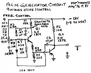
 This schematic is from an old 1976 magazine. It uses germanium transistors, but the circuit looks to me like more common silicon transistors could be used instead. It uses a negative 12V supply, but I would use a positive supply, change the transistors, reverse the diode and use a non-polarized capacitor in place of the 0.47 uF electrolytic.
This circuit looks very similar to the two transistor “Joule Thief” type circuits that we often see on the ‘net. An NPN feeding into a PNP, and the C2 feedback capacitor to make it oscillate. The collector load resistors are 100k and 10k, At 12V, more than a milliamp could flow through R6, but since that transistor is off most of the time, the average current is much lower. In contrast, the 555 would use many milliamps current.
For pulses at audio frequencies, the circuit could probably use a few resistance changes. The reason is that germanium transistors have lower current gain and higher leakage than silicon transistors. I think that R8, R7, R5 R4 could all be increased. And if that is done, C2 may be decreased to keep the frequencies within the audio band.
Also, the output across R10 is medium to high impedance, so I would put another transistor after this as an emitter follower to decrease the output impedance and increase the output current. The transistor might have a 1k to 2.2k emitter load resistor, with its other end connected to the supply and its collector connected to ground. Connecting it this way would minimize the supply current since the voltage across R10 is very low most of the time.
I mentioned the 555, because this circuit could be used as a substitute for the 555 as a very wide range pulse generator. The circuit has no adjustment for the pulse width, but a variable resistor might be added to vary the pulse width somewhat. This resistor might go in series with C2.
BTW, with the negative supply as shown, the pulse is shown as negative going. But actually it would be the opposite, with the output at -12V most of the time, and during the pulse’s peak, it would be approaching zero volts.