default

2012-01-12 FM Microphone- Everything You Wanted To Know And Then Some

I built up this FM microphone from belza.cz.  The circuit is super simple, uses only a single transistor.  The output of the electret condenser microphone is coupled directly to the base of the RF oscillator, and causes the frequency modulation.  However since the microphone has no amplification, it is not sensitive and the user must speak close to the microphone.

Earlier FM Mics I’ve Built

I’ve built several of the two transistor FM microphones that are often seen on the ‘Net.  They typically use a RF stage that is different than the one seen at Belza.cz.  These typically have an NPN transistor, often a 2N3904.  The base is at RF ground, typically by connecting a 1000 pF capacitor from the base to ground.  There are two (or sometimes one) base bias resistors, typically 10k and 6.8k.  The emitter is connected to ground through a 470 ohm resistor.  The collector has the parallel resonant tank connecting it to the positive supply.  This parallel resonant tank is typically a 120 nanohenry (same as 0.12 uH) coil and a 20 pF capacitor connected in parallel.  Along with the transistor’s capacitance, it resonates at the low end of the FM broadcast band [see Note].  The feedback capacitor, typically 4.7 pF, is connected between collector and emitter, and causes the circuit to oscillate.  This stage is preceded by a single transistor to amplify the microphone.  This amplified audio is applied to the base where it changes the transistor’s capacitance and that causes the frequency modulation.  This type of RF stage forms a fairly reliable transmitter.

But the FM mic at Belza.cz is quite different.  It uses a PNP 2N3906.  Again, the base is at RF ground due to C1.  The collector has the coil, but the capacitor(s) for the coil are C2 and C3, connected in series and the center connection is also connected to the emitter.  I’ve built similar RF stages before and been disappointed because they sometimes did not oscillate or they weren’t stable.  I decided I would stick with the more common type without the series capacitors.  But I’ve built several other circuits from Belza, and they all lived up to expectations.  So I decided to try this one for a change.

I made a few changes to Belza’s circuit.  I used a 470 pF and 330 pF in parallel for C1 – it’s an RF bypass cap and is not critical.

To get the right voltage, I used 2.7k for R1 (the 4.7k was too high).  R2 actually measured 360 ohms.  I used a 20 pF NPO (NPO means zero temp coefficient) for C2, less than shown because the other circuits I mentioned use only about 5 pF.  For C3 I used a 36 pF, but when I found that the frequency was too high, I paralleled a 5 pF to it for a total of 43 pF.

The All Important COIL

The coil of the FM microphone is important because it along with the capacitor(s) determines the frequency and stability.  Also it is usually small, in order to keep  the FM mic small.  In order to tune the FM mic, the capacitor can be a variable capacitor, but they are usually much bigger than the fixed ceramic disk and are more expensive.  So many inexpensive FM mics use a fixed capacitor and a coil that can be squeezed or compressed to tune the frequency.  Even if the coil is wound on a coil form with a small tuning slug, it is smaller and may be cheaper than the variable capacitor.  But whatever the coil is, it should have good mechanical stability; the copper wire should be thick enough to support the coil firmly, and the coil should be small and light so it doesn’t pick up vibrations.  Vibrations, also called microphonics, can be heard in the FM signal when it’s quiet.  One way to muffle this is to stuff the coil with a tiny piece of foam rubber and when the coil has been tuned, drop a few drops of paraffin AKA candle wax on it.  The experimenter can use a short piece of soda straw as a coil form, and some hot glue, silicone seal or other glue to hold the coil in place.

One other method of making a coil is to use a spiral shaped trace on a PC board.  This is very stable but is not variable, however it can have multiple taps to give some range of tuning.  We’ll just leave it at that, because it has to be done when the board is made and few experimenters want to make their own boards.

However, I’ve made the equivalent to that by using a short length of 14 AWG or other heavy gauge copper wire, and I bent it into a square shaped single turn coil.  Each side of the coil was about 35 to 40 mm or 1-3/8 to 1-1/2 inches on a side.  This was held up above the circuit board by putting blobs of silicone glue on the board, letting them dry, then mounting the coil on the silicone blobs with more silicone glue.

My coil was at first about 120 nanohenrys, which is typical for these FM mics.  It was 22 AWG solid enameled wire, and about 5 turns, inside diameter of 5 mm or 0.196 inch.  The frequency was up around 94 MHz, too high – I wanted it around 90- MHz.  So I removed the coil and put in one made of 26 AWG solid enameled wire and was 10 turns close wound on a much smaller 0.120 inch diameter air core.  The turns are touching each other so it is quite stable, but then it can’t be squeezed to tune it.  But the inductance is about 200 nanohenrys and the frequency is about 89.8 MHz.

Not shown on the schematic but is absolutely necessary at this frequency is a 0.01 uF ceramic disk bypass capacitor across the power supply lines.  I usually run these FM mics with no antenna because the antenna is connected to the oscillator and any changes to the antenna change the frequency.  Without the antenna the FM mic may be picked up 300 feet or 100 meters away, but the distance is heavily influenced by the battery voltage, which determines the power.  This one uses only 3VDC and draws about 3  mA, which totals only 9 mW, and consequently the signal can’t be heard more than a few dozen feet.  I could add the antenna but I don’t really need the greater range.

Microphone Sensitivity

I was surprised at the sensitivity of the microphone.  It’s not sensitive, but it’s not insensitive.  I can put my “ticking time bomb” circuit a foot away and clearly hear the ticking in the FM radio a few yards away.  I have to talk about a foot or two away, whereas the circuits with the second transistor as microphone amp can pick up sounds a dozen feet away,  So this single transistor circuit can be sensitive enough for use as a close microphone.  One other point that I’ve run into.  The electret condenser microphone is a strange beast.  Its range of sensitivities can be wide, as can its current.  The circuit called for a 4.7k for R1, but I had to use a 2.7k to get enough voltage across this resistor, which determines the transistor’s operating point.  So each microphone will have to have its resistor selected to match it.  In other words, don’t expect the circuit to work good if you put a 4.7k in there and forget to check the voltages.  Like it says in the schematic, there should be about 1.3 volts across the resistor.

Another problem I’ve found with the microphone is its low frequency sensitivity.  The human ear doesn’t respond to low frequency sounds, such as when a door closes and causes the pressure in the room to change.  This circuit has the microphone connected directly to the transistor, so its low frequency response is very good, probably too good.  When some low frequency sound is picked up, it will cause the FM signal to vary widely and this could be a problem.  The circuits that use a microphone amplifier can be limited in their low frequency response by using lower value coupling capacitors, so the frequency response drops below 100 Hz, where there are little or no human voice input.  This circuit doesn’t have that option – you get maximum bass response from the microphone.

Frequency – Changes

One other point that might be a concern.  As more receivers today are all digital, and they have channels that are on the FM frequencies such as 88.1, 88.3, 88.5, etc., it may become harder to pick up one of these FM microphones if it is on a frequency that is not a channel, such as 88.2.  And if it is close enough to a channel it may be picked up but as the battery voltage and/or temperature changes, it may drift to a frequency that can’t be received.  So it might be a good idea to use a coil that can be spread or compressed to adjust the frequency somewhat.

Another way to tune an oscillator is to put a diode across the capacitor, and connect it to a potentiometer so that a variable DC bias voltage can be put across the diode.  But this usually requires more than 3 volts across the diode to give enough tuning range.  If the diode has from 3V minimum to 9V or so, it will give a reasonable range of tuning.  One way to get 9V for the diode is to use a pair of 3V lithium coin cells.  This when added to the 3V supply will give 9VDC.  The diode doesn’t draw any current, but the pot does.  But if the pot is 1 Meg, the current drawn is so low that the coin cells should last for years.  Another cheap way to tune it slightly is to vary the base bias.  But this also changes the power output.

Note: Some information on how to determine the capacitance and inductance for this type of microphone.  Let’s say you want to use a coil with 120 nanohenrys or 0.12 microhenrys.  You can plug this into a calculation on a scientific calculator, and you will come up with the reactance at 90 MHz, the frequency I’ve chosen.IMG_20131201_090327


I multiply 2 times Pi times the frequency 90E6 Hz or 90 Megahertz, times 120E-9 or 120 nanohenrys.  The result givces about 68 ohms inductive reactance.

The capacitor has to have the same reactance at the resonant frequency, so we plug this into a calculation to get the capacitance.IMG_20131201_090214


I divide 1 by 2, by Pi, by the frequency 90E6 or 90 Megahertz, and by the reactance, 68 ohms.  The answer 2.6 E-11 has to have the decimal point moved one to the right, to give 26 E-12 or 26 picofarads.  This is the total capacitance across the coil.  There is a small ampunt of capacitance in the transistor’s collector, about 4 or 5 pF for the 2N3904, so the actual capacitor value should be about 20 to 22 pF.  If the coil can be stretched or compressed, it should give a range of tuning to make the frequency somewhere around 90 MHz at the bottom of the FM band.


Back to experimenting…

default

2013-01-10 Colorful Multitapped Coil

I built this coil, modeled somewhat after the coil I saw in this Youtube video.  It uses 24 AWG solid telephone wire, and the winding color indicates the number of the winding according to the resistor color code: 1 (brown) through 0 (black).  The first and last windings are 5 turns each.  The windings in between are 10 turns as can be seen in the wiring diagram beside the coil.  The core is a TOR-61 core, from allelectronics.com.  I’m going to try to mount it on a small piece of wood with a terminal strip.

Inductances:

BRN to BRN (Start) 0.08 mH

BRN to BRN-RED (gives an invalid negative number)

BRN to RED-ORG 0.695 mH

BRN to ORG-YEL 1.96 mH

BRN to YEL-GRN 3.91 mH

BRN to GRN-BLU 6.6 mH

BRN to BLU-VIO 10.1 mH

BRN to VIO-GRY 14.4 mH

BRN to GRY-WHT 19.5 mH

BRN to WHT-BLK 22.5 mH

BRN to BLK (end) 25.2 mH

The accuracy of the meter I used is not so good at the low and high ends of the measurements.

default

2013-01-09 Remote Control Jammer

This remote control jammer circuit is basically the same circuit as a LED flasher, except that the timing capacitor is much smaller – .001 uF – so it flashes at a much higher frequency, around 38,000 times a second.  The 9V battery is expensive; instead save money.  Change the two IR LEDs from series to parallel and change the battery to four AAA cells in series.  Remove the second IR LED from its existing place and add another 220 ohm resistor to it.  Then connect these across the existing IR LED and 220 ohm resistor.  Both 220 ohm resistors can be reduced to 150 ohms to get more current through the IR LEDs.

default

2013-01-08 Carbon Arc Light

I had a few really old C cell batteries, the old zinc-carbon or LeClanche type.  I tore off the metal jacket and then what was left of the zinc and dirty black powder, leaving the carbon rod, which is used as the positive electrode.  I took two of them and held them with a pliers  in the flame of the stove, to heat them up to a dull red and burn off any tar or paraffin.  Then I connected them to the positive and negative alligator clips of my 3 amp power supply and tried to get them to light up when touched together.

I wasn’t very successful.  I managed to get a few flashes from the contact, but I think the power supply didn’t have high enough current.  I did manage to generate enough RF interference to cause the digital TV to stutter and black out for a second when the rods made contact.

When I was very young and learning about electronics, I did this using a filament transformer for the power source.  The transformer was probably capable of delivering 10 amps or more of current when the arc was started, so it made quite a bit of light.

Historically the carbon arc was the first form of electric light.  It came early in the 1800s when in 1808 Humphry Davy managed to get enough current from the battery to make an arc.  This was shown in the Youtube video History of Electricity from the BBC.

default

2013-01-07 Understanding Transistor Data Sheets

I came across this document, The Handyman’s Guide To Understanding Transistor Data Sheets at the NRAO gov’t site.  It’s a downloadable .PDF file.  This document is great for those wishing to design and build RF and audio amplifiers, but unfortunately it has only a small paragraph at the end on switching, which is what the DC to DC converters such as a Joule Thief do.  But anyone who uses transistors in their projects should become acquainted with the terminology and specifications of the datasheets, so he/she can make an intelligent comparison of the different transistors.

default

2013-01-06 Incandescent Lamp Lifetime

I was discussing using an incandescent lamp for a heater, where the amount of light is not important.  I looked up some info on miniature lamps in the General Electric Miniature Lamp Catalog.  Miniature lamps used to be inside of appliances, and cars, such as in the instrument panel, speedometer, glove box, etc.  Now they have often been replaced by LEDs.

Did you know that the life of a miniature lamp varies inversely as the 12th power of the voltage?  And the candlepower varies as the 3.6th power of the voltage.  That info is from the first page, which also has a graph of these values for different voltage percentages.

I calculated that if I power the lamp with half voltage, the life will be 4096 times its rated life.  So if its rated life is 1000 hours, then at half voltage it should last 4,096,000 hours.  Gee, that’s 467 years!  That beats LEDs by far!

My co-worker retired years ago, but she and her husband lived on the street on which I travel on the way home from work.  During these winter months when it’s dark on the way home, I pass by their house and I see the street address number dimly lit from behind by an incandescent lamp.  The light is probably a 28V or more lamp running from a 16V doorbell transformer.  All these years, probably since the house was built, the same light bulb has been lighting that street number, the amber or orangish glow on 24/7.

This just shows how long an incandescent light will last if you’re willing to sacrifice much of the light output.

default

2013-01-05 Thermocouple Measurements

I had a thermocouple from an appliance lying around in the garage and I decided that it would be a good idea to experiment with it.  It was a used one, but I don’t know what it was from; maybe a water heater.  But a long time ago I had cut off the end that goes into the thermostat, so all that was left was a bare copper tube with a copper wire inside of it – a coaxial cable, so to speak.  It was so old that the copper was all oxidized and turned dark brown, so I had to polish up the end with some sandpaper.

Being that it has been chilly, I can turn on the stove burner and put the thermocouple in the flame.  I clipped on a cheapo DMM, and measured the voltage with the thermocouple’s tip a dull red, and I got about 42 millivolts.  But how much current can this deliver?

I got a 10 ohm resistor and put it across the wires.  The DMM still read 42 millivolts.  It didn’t drop at all, so I went and got a 1 ohm resistor and put it across the wires.  The meter dropped only 2 millivolts from 42 to 40 mV.  That small drop indicates the thermocouple can deliver quite a bit of current.  But at 40 millivolts, the impedance is very low, a small fraction of an ohm.

The big problem is that in order to get enough voltage to run a DC to DC converter, I need to connect at least 20 to 25 thermocouples in series, which will give 0.8 to 1 volt.  And there doesn’t seem to be enough room in the flame to put that many thermocouples together, not to mention that they would cost a few hundred dollars.  Here is one experimenter’s method of generating electricity with thermocouples.

Another way to harvest energy is to use a Peltier junction.  They also produce a low voltage, but not as low as a thermocouple.  Also, it may be possible to use heat to generate IR (infrared) radiation, and that is then harvested by solar photovoltaic cells.

Back to experimenting…

default

2013-01-04 LED Abuser

Not me, the beasty I made is the LED abuser.  Well, maybe me, too.  See the photo.  I had this high voltage transformer I got a few years ago, and I hooked up a power transistor (2SC2334) to the center tapped winding just like a Joule Thief.  The resistor is 180 ohms wire wound.  It draws 1.2 amps at about 4V (the power supply won’t go higher, it current limits a t 1.2A max).  As can be seen it puts out a nice 1/4″ (6mm) arc.  It makes some ozone smell, too.

I got a bag of Agilent (HP) HLMP-3401 yellow (amber) LEDs from Goldmine-elec.com for cheap, and I thought that being they’re a brand name, they would put out a decent amount of light.  Well, they don’t, they’re only bright enough for indicators (See note below).  They make okay light sensors, though.  So I thought that`since I had so many, I would try to burn one out with my LED abuser / arc maker.

I held the LED with a pair of well insulated long nose pliers and put it up to the arc, and watched as the arc jumped between the LED leads.  The LED was slightly flickering, so I turned it around and let the arc go through it in the opposite direction.  COOL!  I now have a fried LED!

But why was it flickering as the arc was going through it?  I connected it up to the power supply and…  It lit up, just like normal.  Huh??  It should have been fried by now!  So I repeated the arcing and then tested the LED on the PS and it lit up, just like normal!

Weird!  I have an LED that can handle several tens of thousands of volts without even a bit of damage.  It has withstood the ultimate test!  Like Dr. Frankenstein said, “It’s ALIVE!  ALIVE!”

…But I probably shouldn’t put this one back in the bag with the rest…

Back to zapping…

Note: I found another use for these amber LEDs.  They work good for protecting the base to emitter junction against excessive voltage.  I soldered two of them in series and put them between the base and emitter of a JT transistor, with the cathode connected to the base.  When the base voltage gets to negative  5 or 6 volts, the LEDs light up and absorb the excess voltage.

default

2013-01-02 “Ticking Time Bomb”

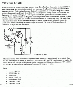
Remember Capt. Hook and the crocodile?  This circuit is almost the same as a flasher, except instead of an LED it uses a speaker.  The result is that it pulses the speaker with a very short pulse of  current.

The circuit uses a 9V battery, but today the 9V battery is too expensive, so I would replace the 9V battery with a single AA cell and a Joule thief to boost the voltage up to about 4 to 6 volts.

The circuit could be changed to a flashing Joule Thief so that the transistors  that do the flashing also boost the voltage.

Update Jan 5

I built the circuit on a piece of wood with some tiny screws as the solder points.  I made a few changes to it as follows.  I changed the BC557 PNP to a SS8550 1 amp audio output transistor.  I changed the BC547 to a PN2222A.  I changed the 2.2 uF electrolytic to two 1 uF monolithic ceramic capacitors in parallel.  I changed the 200k pot to a 600k pot.  Instead of 9V, I set the power supply at 4.5VDC, which seemed to be loud enough.

I powered it up and found that it did, indeed, tick like a time bomb.  I could vary the tick rate from less than 1 per second to a low buzz of maybe ten per second.  But the current on the power supply’s meter was too low to read, so I put the DMM in series with the power supply lead.  The meter would read zero until a click, then jump up a little bit, but it wasn’t readable.

To get a stable reading, I put a 10 thousand uF capacitor across the time bomb’s supply leads, and a 100 ohm resistor in series with the positive lead.  This filtered out the spikiness of the supply current.  When I adjusted the click rate for about 2 a second, the current was under 2 milliamps at 4.5V.  When I increased the click rate, the current went up to about 5 milliamps.

That current is so low that it would run for a week or more using three AAA cells.  It would be really easy to run it using a single AA cell.  If I want to keep the circuit as it is, I would have to add a Joule Thief to convert the 1.5V to 4.5V.  That’s easy to do, since the average output current would be 5 milliamps or less, so accounting for efficiency, the JT would draw about 30 milliamps at 1.5V from the AA cell.  The output of the JT is rectified and filtered, and a 4.7V zener would be used as a shunt regulator.  The time bomb would then be connected across the zener.

The only thing that I don’t like about this is that the shunt regulator wastes most of the power.  I could redo the JT so that it is shut down when the voltage gets up to 4.5V, so between clicks, it doesn’t waste much power.  But this just adds more complexity to the circuit that already is getting complicated.  A better way to go would be to make a flashing Joule Thief, but instead of an LED, it drives a speaker.  The circuit itself does the conversion along with the

Tick.. Tick.. Tick..

Back to experimenting…

default

2013-01-01 Happy New Year! Robotics Raceway

I was out working on wiring at our other campus, and was surprised to find that the floor was wired.  Yes, the floor was wired.  Well, the floor had wiring on it.  This was for the class where they teach robotics and the wire is there for the robot cars to follow.  I haven’t investigated to find out anything more, but for now I know that these little critters can follow the wiring that’s taped to the floor.  There was other information about robotics written on the whiteboards, like symbols for resistors transistors, capacitors, relays, 555 chips, etc, etc, etc.  There were piles of robot magazines on the counter.  To me, this class sounds much more interesting than the average college class!

© RustyBolt.Info/wordpress
CyberChimps