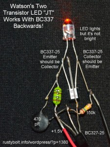
 I looked at the photo in the Yahoo Group Joule Thief, and saw that it was working, but then I noticed that the BC337 transistor looked like it was backwards. I had to look at it again to make sure that I was seeing it correctly. Yup, it looked like it was in backwards, but the LED was lit up. I thought that it shouldn’t be working, so I decided to replicate the circuit and see if my replica would also work.
I used the same two transistors, the same capacitor and resistor, and the same color amber LED. I couldn’t find a 120 microhenry ‘green blob’ choke so I used a 180 uH instead. I soldered it together so the parts were roughly in the same location as in the photo, see my attached pic. I connected it up, and it worked! But the LED wasn’t bright, and it was drawing very little current from the supply, only 5 milliamps.
I unsoldered the BC337 and soldered it back in the correct way. This time, at 1.5V, the supply current was 10 mA, still not enough but twice as much as when it was backwards. The frequency was 18kHz and the LED was much brighter. I put another 150k resistor in parallel with the original, and the LED got brighter and the supply current went up. I think for my replica, an better choice for this resistor would be about 47k.
I thought about how the transistor was working backwards. When the emitter junction is used as the collector, it is reverse biased. The emitter to base junction has a breakdown voltage of only 5 volts. But since the supply voltage is only 1.5V, and the LED prevents the collector voltage from going over 5V, there is no problem with a rating of only 5V maximum collector voltage. So the circuit will work, however the transistor will have very low current gain because it was not made to operate in this mode. That’s the reason why the LED was dim.
Back to experimenting…