default

2012-04-13 Friday the 13th – Old HP Test Equipment

on April 13th, 2012 by - Comments Off on 2012-04-13 Friday the 13th – Old HP Test Equipment

Well, it’s Friday the 13th.  We just had a Friday the 13th just 13 weeks ago, and we will have another one in 13 weeks.  Wow!  That’s almost spooky!

Friday really was Friday the 13th for me and my co-workers.  We had several network problems, one which required me to run from one building to another, holding my umbrella tightly to keep it from blowing away as the rain came down heavily.  Pants got wet from the knees down.   The rain storm passed through quickly so everything was calm by the end of the day.   No noticeable thunder, lightning or hail, though.

Vintage HP Test Equipment  When I was a teenager a neighbor kid and I would hang out at the shop in the garage of a neighbor who was a ham.  He had a lot of HP test equipment and the usual TEK and other high quality stuff, like General Radio gear.  We got to use it if we helped him get a few other things done.  We also got to take a ride in his private airplane, and ride to the airport in his Porsche.  🙂

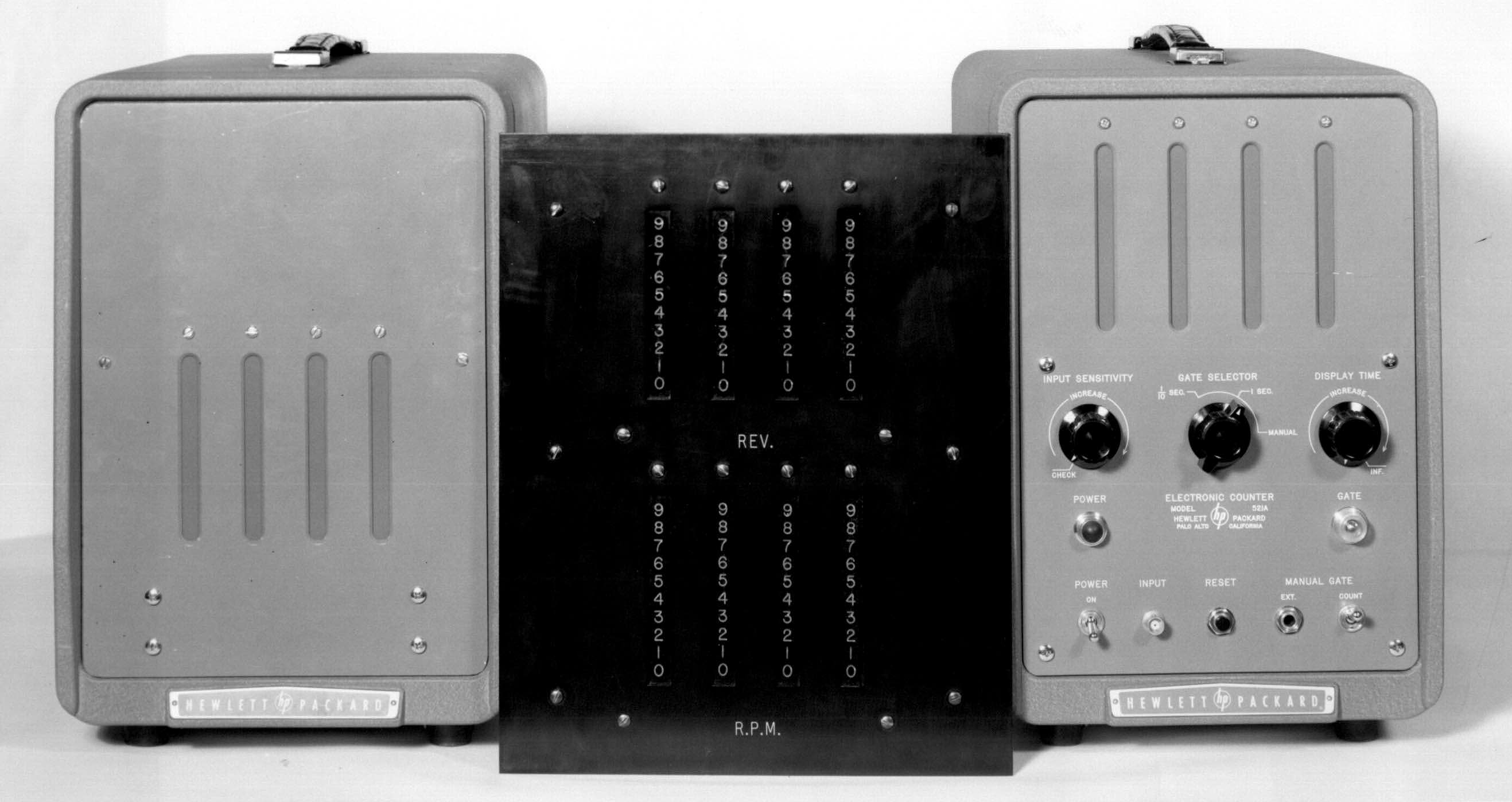
On occasion he would get old test equipment to play with, usually on the condition that it got repaired, or at least troubleshot to find out what was wrong.  Some of it was very good quality for its day, just that it had long been superceded by newer versions.  An example is this ancient HP 521A frequency counter, which used neon lights in a long column with a mask in front with the digits etched into it.  Hey, nothing wrong with that; it was a lot easier to read than a binary display!  0000, 0001, 0010, etc.  There is much more of the same, including manuals in www.HPArchive.com

The ‘wiggle stick’ meters were Simpson, Triplett, Weston, and of course HP.  The John Fluke Company started making high quality test equipment, one of which was the differential voltmeter.  This is a later version; the earlier ones were bigger and heavier.  Basically the operator was doing manually what is automatically done today.  But you could get accuracy in the millivolts, something you couldn’t do with a regular wiggle stick meter.

One type of test equipment that he had was General Radio gear.  This was top of the line for its day, much of the accuracy was due to accuracy in construction and quality in workmanship. One innovative piece of General Radio gear was the GR 874 connector.  It was hermaphrodite; any connector would fit any other connector.  How?  Well, take a look.

Back then the RF equipment for UHF and above was marked KMC/s (kilomegacycles per second) because Hertz and Giga- had not yet been adopted as a standard.  See this NIST page for more info.

Quantsuff sent me a link to a Youtube video of a very large digital display cranking away.  Very innovative.  They will never have a shortage of coffee mug holders!

Back to experimenting…

default

2012-04-12 A 12 LED Joule Thief Lantern

on April 12th, 2012 by - Comments Off on 2012-04-12 A 12 LED Joule Thief Lantern

I blogged this for a neophyte on Energetic forum.

If you’re going to use an existing lantern, then you may have a lot of modifications, since a lantern usually has several cells in a battery pack, which gives you a long battery life.  If you reduce the number of cells, the battery life will be considerably reduced (remember that the battery voltage cannot be as much or more than the LED voltage).  joule Thiefs are only about 50 to 60 percent efficient, so you will lose up to half the power in the circuit.  You could instead use a more efficient circuit such as my SJT.

For 12 regular LEDs, you could just buy a couple of the 9 LED flashlights for about 2 dollars apiece, disassemble them and remove the circuit board, and remove a few of the LEDs from each.  Then build a more powerful JT circuit to give enough juice to run all 12 at their rated brightness.  You will have to do some serious work to get enough power out a simple JT circuit to put out up to 240 milliamps to the 12 LEDs.

If you’re going to start from scratch and not use something already assembled, you have many more options available.  One option is to just put four JT circuits, each with three LEDs, built into the same case.  A good idea is to use more powerful 10mm LEDs, as Quantsuff did in his project.  Go here and scroll down to Sample Retrofits.

Back to experimenting…

default

2012-04-11 Low Power DC-DC Joule Thief Conversion

on April 11th, 2012 by - Comments Off on 2012-04-11 Low Power DC-DC Joule Thief Conversion

Many experimenters have this “brilliant idea” of using a Joule Thief to boost the voltage of a low voltage, low power device such as a solar cell or Peltier TEG, to a higher voltage.  I’ll go over what I’ve learned in my experiments with Joule Thiefs.

Conventional JT performance  See a photo of a conventional JT at the right.  The conventional JT works good at converting 1.5V from a single cell to 3.3 volts to light a white or blue LED.  The single transistor, single LED circuit has been optimized for these voltages.  If you take a mostly used cell and put it on a JT, its voltage may drop to 1 volt, and the LED may be much dimmer than it was at 1.5V.  When the cell voltage drops to 0.75V or half of a fresh cell’s voltage, the LED may be very dim, with barely enough light output to make it useful for seeing anything.  The cell’s chemicals are depleted, the chemical reactions drop off, the cell’s internal resistance increases, and consequently the voltage drops down to 1/2 volt, where the dim light gets weaker and the light output is not useful other than the LED indicates that the circuit is still connected to the cell.   After the cell’s voltage drops below 1/2V, the LED may glow very dimly for quite awhile, but it is drawing a small fraction of a milliamp from the cell, and the JT circuit will not be able to start again.  I would assume that the average experimenter has seen his JT circuit pass through these stages as the 1.5V cell is depleted.

A major player in the dropoff of the LED’s light output is that as the voltage drops, it leaves the JT’s optimum point, and the JT would require more base bias current to put out the same amount of light.  More base current means the 1000 ohm resistor woulld have to be reduced until the LED’s light output is brought up to adequate level.  I’ll have to re–explain what I’ll call Watson’s Inverse Perverse Law, or the law of rapidly diminishing returns.  Let’s say the cell voltage drops from 1.5V down to half that, to 0.75V.  Since the voltage is half, the cell will have to put out twice the current to keep the LED lit the same.  But half the voltage at twice the current means the cell sees the JT’s DC resistance as one quarter of what it was.  We need four times as much base current, so the base resistor has to be reduced.  You’re thinking that 1/4 of 1000 is 250 ohms, which would be right if the  base had zero forward voltage.  But it has 0.6V forward voltage, which when subtracted from 0.75V, leaves only 0.15V across the resistor.

Before, the 0.6V was subtracted from the cell’s 1.5V leaving 0.9V across the resistor.  0.9V divided by 1000 ohms is 0.9 milliamp or 0.0009 amp.   Now with 0.15V, if we want 0.0009 amps to flow, we divide 0.15 by 0.0009 and we get 166.666.. or 167 ohms.

This assumes that the transistor has the same current gain at the lower voltage.  But the transistor does not, so its base needs even more current so the resistor has to be further reduced.  How much depends on the transistor’s characteristics.  If it is a BC337, PN2222A or 2N4401, the transistor’s thirst for more base current may be satisfied by a moderate reduction of the resistor.  If the transistor is a 2N3904, BC547, 2SC1815 or similar, the transistor was already pushed past its limits at 1.5V, so at half that voltage it will never be able to put out as much, even if the resistor is reduced to zero ohms.  I would take my wire cutters and snip that 2N3904 out and discard it, and solder in a better choice.  You may not like my actions and you’ll try to make that wimpy 2N3904 do what it can’t do, but that’s your choice.  Don’t say that you haven’t been made aware of the problem.

But will the BDC337, 2N4401 or PN2222A transistor put out enough light with a resistor less than 166 ohms?  It depends on other factors in the JT circuit.  If the coil’s primary winding has very low resistance, then the transistor might be able to put out enough light with less resistance.  I would put a 500 ohm pot with a 47 ohm resistor in series in place of the 1k resistor.  Then at a supply voltage of 0.75V, I would try to get as much light from the LED.  I haven’t tried this, but I suspect that the pot might have to be turned down to much less than 167 ohms, maybe below 100 ohms, depending on the transistor.

I haven’t tried this, but I’ll see if I can set up a test jig and try it with a few different transistors.  Meanwhile here is a list of the transistors that I would try, with my opinion of the best choices at the beginning and the worst choices at the end.

1.  2SD965 or KSD5041 – Can handle 5 Amps – that’s not a typo!

2.  2SC2500D – Good for 2 Amps, really puts out the current.

3.  SS8050 – good for an amp and a half.

4.  BC337 -Good for up to 800 milliamps.

5.  2N4401, PN2222A – A solid workhorse transistor, good for up to a half amp.

6.  2N3904, BC547 – If you put 4 or 5 of them in parallel, they may put out as much as a BC337.

Back to experimenting…

default

2012-04-10 Watson’s Tentacle Power Cord

on April 10th, 2012 by - Comments Off on 2012-04-10 Watson’s Tentacle Power Cord

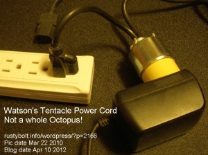
I made a few of these in early 2010, and they are very handy to have around.  I can use power strip sockets that would normally not be usable for a ‘wall wart’ adapter, and the power cord frees up a power strip outlet that would otherwise be used for the adapter.  I’m not sure if they are legal, but they work great.

default

2012-04-09 Meek’s Mk. 21 Mod. 1 Regen Receiver

on April 9th, 2012 by - Comments Off on 2012-04-09 Meek’s Mk. 21 Mod. 1 Regen Receiver

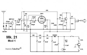
The 1000 character limit of the Yahoo “regenrx” Group comments makes it necessary for my comment to go here.  Also, I’d like to post the schematic here since they tend to drift away, never to be seen again.

My major complaint about this receiver is that it uses a FET on the antenna input.  FETs and CMOS devices are easily damaged by static electricity.  In an attempt to add protection, the designer used two 1N5401 rectifier diodes antiparallel, to limit any electrical surges from the antenna to less than a volt when these diodes conduct.  The problem is that the diodes have a high capacitance with no bias voltage, so they will load down the antenna.  They also will have a tendency to be damaged by a lightning storm.

We Need More Info  Unfortunately nothing is said about the antenna, what kind, how long, etc.  In fact nothing is said about the receiver, what frequencies or band it receives,  etc.  Assuming that the antenna is a long wire with a reasonably low impedance, I would remove the diodes.  I would then replace them with an RF choke, which uses heavy wire so its DC resistance is low, thus giving any lightning induced voltages a low resistance path to ground.  And that is also important: the set must have a good ground.

If the receiver has a relatively narrow band of reception, it would be possible to tune this RF choke to the center of the band with a capacitor in parallel, and then reduce the Q of the tank circuit by putting a resistor across it, so that the tank circuit has a broad peak across the whole band.

Shock Hazard  Another of my complaints about this receiver is that it uses a pair of headphones that are connected directly to the receiver.  This receiver is line operated, the AC power line is directly connected to the receiver’s ground.  The headphones are directly connected to this ground.  It’s a complicated story, but the simple explanation is that the  ground of the AC line is not always at ground – it can be many volts above ground.  Any device that can contact the human body can pose a shock hazard.  if a wire’s insulation is cracked or frayed, there can be a serious danger of shock.  A pair of headphones on sweaty skin can conduct enough current to render a person unconscious.

Also, this headphone set is connected to the B+ high voltage of the set, with only a .01 uF capacitor to block the high voltage DC from going to the headphones.  If the capacitor were to fail, there could be a serious shock hazard.  At the minimum, I would put a transformer between the receiver and the headphones, with the headphone side left ungrounded.

Nothing was said about the vacuum tube, a 9001, which is a number that I’ve never heard of.  It’s definitely not a standard number like those found on most tubes.

Update May 24, 2012  Mr. Meek continues to post designs that are puzzling.  I can’t ever remember seeing a schematic that was complete, in other words had enough information to determine what frequency it received and/or what coils were used, now many turns, etc.  Then later the schematic disappears just like it appeared.

Back to pondering…


default

SS2012-04-08 Watson’s Nearly Disposable Joule Thief Light

on April 8th, 2012 by - Comments Off on SS2012-04-08 Watson’s Nearly Disposable Joule Thief Light

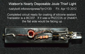
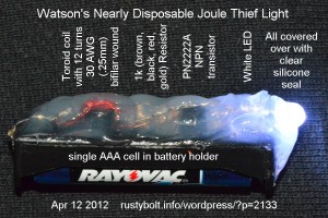
Clear Silicone seal does wonders when it comes to weatherproofing and sealing against moisture.  I used it to cover up and protect the Joule Thief parts on this nearly disposable flashlight.

Components  I wound two six inch lengths of 20 AWG (0.25mm) solid enameled magnet wire (bifilar wound) onto a  0.25 inch outside diameter ferrite toroid.  This core was a T231212T from Surplussales.com.  They were about $.25 (US) apiece.

The transistor was an everyday, common PN2222A, often mistakenly called a 2N2222A.  The resistor was the standard 1000 ohm or 1k, 5%, 1/4 watt resistor.

I inserted a AAA cell to make sure it was working properly and then I covered the whole circuit with clear silicone seal, to protect the components and waterproof them, and set it aside to dry.  A few hours later I had my nearly disposable Joule Thief flashlight.

I didn’t use an on/off switch; I decided the user could use a piece of paper folded in half between the contacts to turn it off.  Or else, just remove the AAA cell.  Most of the cost was in the battery holder, which was about a dollar.

default

2012-04-06 LTA Hangar – Another One Bites The Dust

on April 6th, 2012 by - Comments Off on 2012-04-06 LTA Hangar – Another One Bites The Dust

Another Hangar at the former Marine Corps Air Station, Tustin, California, has gone to the scrap heap of history this week.  The demolition ‘dozer ripped the steel beams out from the walls, twisting them like pretzels.  Every time the ‘dozer pulled out a beam, the whole hangar lurched and loudly popped, banged and groaned as steel beams bent and the structure collapsed.

Over the years since the former air station was  closed and turned over to local governments, portions of the property have been developed into commercial and residential developments.  Apparently after this hangar is gone, there will be further development.  This was one of the smaller hangars on the “LTA” (lighter than air) base as the locals knew it; the two huge blimp hangars are still standing, but for how long, who knows?  I hope they’re rescued and made into historical monuments.

default

2012-04-05 Choosing Diodes for Joule Thiefs

on April 5th, 2012 by - Comments Off on 2012-04-05 Choosing Diodes for Joule Thiefs

Note (from yesterday’s blog):

I have seen many good Joule Thief projects mistakenly use the 1N4003 series rectifier, which is made for 50 or 60 Hz, and has a slow recovery time.  I have put a 1N4003 in parallel with a 1N4148, and found that the Joule Thief’s performance often drops.  This is because it was not made to do a good job of rectification at 50 or 60 kHz, which is a thousand times higher frequency. It should not be used at frequencies higher than audio frequencies*.

If you can buy some, use the 1N5817 Schottky 1 Amp rectifier instead.  But 1N5817s are not found at the average electronics store, so an alternate choice is to use 2 or more 1N4148 diodes on parallel (see below for maximum ratings).  Putting 2 or more in parallel gives more current handling capability and  less voltage drop, and less wasted power.  I seldom see any projects with 2 or more of these or any other diodes in parallel, even though they are dirt cheap and are available at any Radio Shack store.

Another Schottky diode for currents up to a half amp is the BAT85.  But it’s even less common than the 1N5817.

The 1N4148 is rated at a maximum of 75 volts reverse voltage, and 75 milliamps forward current.  But the manufacturers often have their own substitute diode.  For example, Vishay Siliconix calls it a V4148, and Fairchild Semi calls it a F4148.  These substitutes may have a higher forward current, higher peak forward current, higher reverse voltage, and lower reverse recovery time than the 1N4148 specifications call for.   Essentially you’re getting a higher performance compared to the original 1N4148.  But it’s still not capable of handling a full amp, like the 1N5817.

Another common diode number given for projects is the 1N914.  Long ago in projects using diodes, the specifications of the 1N914 were essential for diodes, but in the decades since, the advances in technology have made diodes that surpass those specifications, one being the 1N4148.  But the two numbers became synonymous and often the parts list called for “1N914/1N4148” in an either/or manner – one would work equally as well as the other.  So makers often sold the same diode, but labeled differently depending on what the buyer wanted.  Their specifications were similar enough to freely substitute one for the other.  Their specifications were so similar enough that Fairchild put these diodes all on the same datasheet.

But even though these diodes are “high conductance” that doesn’t mean that they can meet the demanding needs of the Joule Thief, where currents are much higher than 100 mA.  That’s why the 1N5817 or even the 1N5820 (3 amp diode) are commonly used for switching power supplies.

* There is an exception to that.  If you are in need of a high capacitance diode to use as a varicap or variable capacitor, then the 1N4003 series may be able to do the job.  It may have several tens of picofarads of junction capacitance when reverse biased, and of course that changes with the reverse bias voltage, which is how the capacitance is varied.  Sometimes varicaps are mistakenly called varactors.  A varactor is used not for a variable capacitor, but in a frequency conversion circuit.

default

2012-04-04 Nixie Jewelry, Clocks, Etc.

on April 4th, 2012 by - Comments Off on 2012-04-04 Nixie Jewelry, Clocks, Etc.

I got a link from Quantsuff, about making jewelry out of Nixie tubes.  Bill ‘Botronics‘ Sherman replied that Nixie tubes need 140 to 170 volts at 2 milliamps.  Meanwhile, I’ve got ten thousand or more of the Dionics DTN-205 transistors in my parts bins that were made for driving Nixies and VFDs.  I liked Bill’s single Nixie clock, it reminds me of some old HP test equipment.

Quantsuff has been making schematics at Circuitlab.com, here is his latest.  I think that six LEDs are going to be a very big burden for a 1N4148, which is going to have a very high forward voltage drop; the best analogy that I can think of is trying to fill the sink (LEDs) through a soda straw (diode).  I have often noticed that when I put a second 1N4148 in parallel with the original one, it helps and the LED will get somewhat brighter.  This indicates to me that the single one is being pushed past its limits, and a higher current diode is needed (see my note below).  The 1 amp Schottky diode (1N5817) will give much better performance, especially if you use a 2SC2500.  You will need to put 4 or 5 2N4401s in parallel to equal the 2SC2500.  Get the highest gain 2SC2500D if you can – I’ve found they do a very good job of lighting multiple LEDs.

Speaking of parts, I ordered some IRFZ34 MOSFETs from Avnet, and they notified me this late afternoon that the parts had been shipped.  Oddly, though, the parts were sitting on my doorstep when I got home, even before they notified me!  Could this be an example of teleportation? 😉

Speaking of clocks and jewelry, one of the guys at work has a wristwatch that has a dark face, and when he taps the face, it lights up blue and white LEDs that indicate the time.  Looks cool, but will the batteries last long?  He says the LEDs of today use much less power than the LED watches of decades ago, so it shouldn’t be a problem.  Decades ago, Hewlett Packard came out with the HP-01 watch, which used LEDs, but it was extremely expensive – in the late ’70s, $650 was a lot of money.

Speaking of clocks, I saw somewhere that a girl had invented a cool alarm clock that has wheels.  When the alarm goes off, the clock jumps off the table and rolls across the floor, forcing you to get out of bed to shut it off.  I think the name is Clocky.  I saw another alarm clock with a similar idea.  The clock has a propeller that’s inserted in the hole in the top, and when the alarm goes off, the propeller takes off and lands across the room, and the alarm won’t stop until you put the propeller back in the hole.

I got a copy of Cy Tymony’s book “Sneaky Uses For Everyday Things”, and I’ve been perusing the pages.  In one section he shows how to build a crystal radio from a penny.  The penny is heated to form a copper oxide layer, which acts as a rectifier.  Someday I might try that, but I’d rather use a germanium diode for a detector.  The book is for those of us who have to go to extreme lengths; for example it shows how to make wire from aluminum foil or from the spring in a ballpoint pen (that must be difficult, because the steel is so springy).  I found the survival techniques section to be the most useful.  The book is paperback and about a half inch thick. It’s full of black and white hand drawn illustrations, which, in my opinion, would have been better if they were real pictures.  I have ordered but not received a few of his other books, which, I’m assuming, are probably similar.

Note: The note became so long that I gave it its own blog following this one.


default

2012-04-03 Sneaky Sneakier Uses For Everyday Things

on April 3rd, 2012 by - Comments Off on 2012-04-03 Sneaky Sneakier Uses For Everyday Things

I ordered some books from Amazon, most of them being Cy Tymony’s “Sneaky Uses for Everyday Things” series.  So far I’ve received three books, and one is three times thicker than the others.  It turned out that this book is really three books under the same cover.  It’s ISBN: 978-0-7407-8424-8.  From what I’ve read, it seems that there is some duplication between books.

Everything is preceded by “sneaky”, for example sneaky radio receiver, sneaky compass, etc.  I’ll not use that term.

The main piece of equipment for many projects is a cassette tape recorder that has been se to record and pause.  This turns it into a monitor so that anything plugged into the microphone jack is amplified and also sent to the earphone jack.  The author uses this to make a ‘radio receiver’ that really doesn’t receive radio waves.  The output of a small radio is connected to a large loop of wire that acts to make a magnetic field in the room.  This recorder then picks up the magnetic field, but this is not really receiving radio waves.

In another communications device, the radio is used to modulate the light from a LED and batteries, which sends out a light beam.  This is received by a photocell that is plugged into the microphone jack of the recorder and amplified to drive an earphone.

Another project is a microphone.  This is made from pencil leads that are mounted inside of a cardboard box that originally held paper clips.  A battery powers it, and an earphone is the used to transform the electric signal back to audio.

In addition to the projects, there is a section on “sneaky survival techniques.”

© RustyBolt.Info/wordpress
CyberChimps