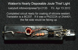
 Many experimenters have this “brilliant idea” of using a Joule Thief to boost the voltage of a low voltage, low power device such as a solar cell or Peltier TEG, to a higher voltage. I’ll go over what I’ve learned in my experiments with Joule Thiefs.
Conventional JT performance See a photo of a conventional JT at the right. The conventional JT works good at converting 1.5V from a single cell to 3.3 volts to light a white or blue LED. The single transistor, single LED circuit has been optimized for these voltages. If you take a mostly used cell and put it on a JT, its voltage may drop to 1 volt, and the LED may be much dimmer than it was at 1.5V. When the cell voltage drops to 0.75V or half of a fresh cell’s voltage, the LED may be very dim, with barely enough light output to make it useful for seeing anything. The cell’s chemicals are depleted, the chemical reactions drop off, the cell’s internal resistance increases, and consequently the voltage drops down to 1/2 volt, where the dim light gets weaker and the light output is not useful other than the LED indicates that the circuit is still connected to the cell. After the cell’s voltage drops below 1/2V, the LED may glow very dimly for quite awhile, but it is drawing a small fraction of a milliamp from the cell, and the JT circuit will not be able to start again. I would assume that the average experimenter has seen his JT circuit pass through these stages as the 1.5V cell is depleted.
A major player in the dropoff of the LED’s light output is that as the voltage drops, it leaves the JT’s optimum point, and the JT would require more base bias current to put out the same amount of light. More base current means the 1000 ohm resistor woulld have to be reduced until the LED’s light output is brought up to adequate level. I’ll have to re–explain what I’ll call Watson’s Inverse Perverse Law, or the law of rapidly diminishing returns. Let’s say the cell voltage drops from 1.5V down to half that, to 0.75V. Since the voltage is half, the cell will have to put out twice the current to keep the LED lit the same. But half the voltage at twice the current means the cell sees the JT’s DC resistance as one quarter of what it was. We need four times as much base current, so the base resistor has to be reduced. You’re thinking that 1/4 of 1000 is 250 ohms, which would be right if the base had zero forward voltage. But it has 0.6V forward voltage, which when subtracted from 0.75V, leaves only 0.15V across the resistor.
Before, the 0.6V was subtracted from the cell’s 1.5V leaving 0.9V across the resistor. 0.9V divided by 1000 ohms is 0.9 milliamp or 0.0009 amp. Now with 0.15V, if we want 0.0009 amps to flow, we divide 0.15 by 0.0009 and we get 166.666.. or 167 ohms.
This assumes that the transistor has the same current gain at the lower voltage. But the transistor does not, so its base needs even more current so the resistor has to be further reduced. How much depends on the transistor’s characteristics. If it is a BC337, PN2222A or 2N4401, the transistor’s thirst for more base current may be satisfied by a moderate reduction of the resistor. If the transistor is a 2N3904, BC547, 2SC1815 or similar, the transistor was already pushed past its limits at 1.5V, so at half that voltage it will never be able to put out as much, even if the resistor is reduced to zero ohms. I would take my wire cutters and snip that 2N3904 out and discard it, and solder in a better choice. You may not like my actions and you’ll try to make that wimpy 2N3904 do what it can’t do, but that’s your choice. Don’t say that you haven’t been made aware of the problem.
But will the BDC337, 2N4401 or PN2222A transistor put out enough light with a resistor less than 166 ohms? It depends on other factors in the JT circuit. If the coil’s primary winding has very low resistance, then the transistor might be able to put out enough light with less resistance. I would put a 500 ohm pot with a 47 ohm resistor in series in place of the 1k resistor. Then at a supply voltage of 0.75V, I would try to get as much light from the LED. I haven’t tried this, but I suspect that the pot might have to be turned down to much less than 167 ohms, maybe below 100 ohms, depending on the transistor.
I haven’t tried this, but I’ll see if I can set up a test jig and try it with a few different transistors. Meanwhile here is a list of the transistors that I would try, with my opinion of the best choices at the beginning and the worst choices at the end.
1. 2SD965 or KSD5041 – Can handle 5 Amps – that’s not a typo!
2. 2SC2500D – Good for 2 Amps, really puts out the current.
3. SS8050 – good for an amp and a half.
4. BC337 -Good for up to 800 milliamps.
5. 2N4401, PN2222A – A solid workhorse transistor, good for up to a half amp.
6. 2N3904, BC547 – If you put 4 or 5 of them in parallel, they may put out as much as a BC337.
Back to experimenting…