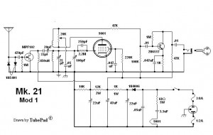
 The 1000 character limit of the Yahoo “regenrx” Group comments makes it necessary for my comment to go here. Also, I’d like to post the schematic here since they tend to drift away, never to be seen again.
My major complaint about this receiver is that it uses a FET on the antenna input. FETs and CMOS devices are easily damaged by static electricity. In an attempt to add protection, the designer used two 1N5401 rectifier diodes antiparallel, to limit any electrical surges from the antenna to less than a volt when these diodes conduct. The problem is that the diodes have a high capacitance with no bias voltage, so they will load down the antenna. They also will have a tendency to be damaged by a lightning storm.
We Need More Info Unfortunately nothing is said about the antenna, what kind, how long, etc. In fact nothing is said about the receiver, what frequencies or band it receives, etc. Assuming that the antenna is a long wire with a reasonably low impedance, I would remove the diodes. I would then replace them with an RF choke, which uses heavy wire so its DC resistance is low, thus giving any lightning induced voltages a low resistance path to ground. And that is also important: the set must have a good ground.
If the receiver has a relatively narrow band of reception, it would be possible to tune this RF choke to the center of the band with a capacitor in parallel, and then reduce the Q of the tank circuit by putting a resistor across it, so that the tank circuit has a broad peak across the whole band.
Shock Hazard Another of my complaints about this receiver is that it uses a pair of headphones that are connected directly to the receiver. This receiver is line operated, the AC power line is directly connected to the receiver’s ground. The headphones are directly connected to this ground. It’s a complicated story, but the simple explanation is that the ground of the AC line is not always at ground – it can be many volts above ground. Any device that can contact the human body can pose a shock hazard. if a wire’s insulation is cracked or frayed, there can be a serious danger of shock. A pair of headphones on sweaty skin can conduct enough current to render a person unconscious.
Also, this headphone set is connected to the B+ high voltage of the set, with only a .01 uF capacitor to block the high voltage DC from going to the headphones. If the capacitor were to fail, there could be a serious shock hazard. At the minimum, I would put a transformer between the receiver and the headphones, with the headphone side left ungrounded.
Nothing was said about the vacuum tube, a 9001, which is a number that I’ve never heard of. It’s definitely not a standard number like those found on most tubes.
Update May 24, 2012 Mr. Meek continues to post designs that are puzzling. I can’t ever remember seeing a schematic that was complete, in other words had enough information to determine what frequency it received and/or what coils were used, now many turns, etc. Then later the schematic disappears just like it appeared.
Back to pondering…