I was reading the comments in this Instructable and found a comment by Colin55 (Colin Mitchell of Talkingelectronics) showing a Joule Thief circuit that used a bolt and nut for a coil form. He wound 200 turns on the bolt for the primary winding and 40 turns for the feedback winding. One thing I think is a big mistake: he used a 9V battery, which is far too expensive and could be replaced by one or two AA cells for a small fraction of the cost. Also by rearranging the 12 LEDs in series – parallel, the 9 volt Joule thief circuit could be replaced by a few resistors and it would even be more efficient.
 But back to my circuit. I decided that I should try to replicate the coil, even though I would definitely not replicate the circuit. Instead I would use a conventional Joule Thief circuit with a 1.5V cell (or power supply).
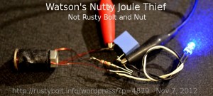
I scrounged a 1/4 inch by 1 inch long carriage bolt and nut – this duplicated the coil shown in the link, and wound a few layers of black electrical tape over the threads to prevent them from touching the wire and doing damage. I then wound 40 turns of 28 AWG enameled wire onto the bolt, and brought out the loop of wire. I continued to wind the remaining 200 turns onto the bolt. Then I covered the whole winding with some more electrical tape to protect it. The 200 turn winding measured 160 uH and the feedback winding measured 4.6 uH.
I tack soldered a conventional JT to the coil. I used the typical PN2222A transistor, a 1k resistor and the light blue ‘box’ is a 0.22 uF capacitor across the power supply leads, optional but its use is a prudent addition. The LED was a blue 5mm. I didn’t show it in the picture, but I added a 1 ohm resistor in series with the LED lead, so I could measure the LED current.
Results
I connected it to the power supply which was set at 1.5VDC. It flashed on and off erratically, it didn’t want to stay on. I lowered the voltage down to 1.25V and it became stable and lit the LED constantly. I measured the LED current and got 4.8 mA. I increased and decreased the supply voltage, and I found that when I went above 1.2V the LED current went down, which is contrary to what one would expect. I backed off to 1.2V then went below, and the LED current began to go down. So there seems to be a broad optimum point at 1.2V where the LED current stays at 4.9 mA. This anomaly is something I’ve never seen it the dozens of previous JTs I’ve experimented with. The supply current at this point was 62 mA and the frequency was 63 kHz.
The typical conventional JT that uses a toroid for the coil will draw 60 to 80 milliamps from the power supply and put out about 17 milliamps to the LED, for an efficiency of about 50 to 60 percent. This Joule Thief is drawing 62 milliamps, low but typical, but putting out less than one third of the current to the LED, which is very inefficient. The obvious explanation is the coil, for it’s the only component that is different from a typical JT. This coil uses a solid iron or steel core, with no laminations or powder. To me this is the reason why it wastes so much power and is so inefficient.
Back to the optimum point. I think that the reason for this anomaly is that the coil inefficiency causes losses to increase as the supply voltage and current increases. It could be caused by core saturation. The difference in the turns ratio (not 1:1) could be a contributing factor In any case, the conclusion I come to is that this coil is a very poor design even though itt does work, but the coil has so much loss that it should not be considered when building a Joule Thief. An alternative is to wind the wires onto an air core coil. This is done by winding the wires onto an AA cell, then removing the cell and tying the coil with wire ties, tape or even dental floss. This coil will be much less lossy than the steel bolt and nut. And you don’t have to use the not so rusty bolt and nut, saving you money (or preventing your gate from falling of its hinges because you stole one of the bolts to make your coil!)
Back to experimenting…