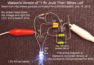
 I received a Google Alert with a link to a Youtube video showing a blinking Joule Thief and its schematic. I examined the schematic and found that the collector of the PNP was connected to positive, and the collector of the NPN was connected to the negative. These are opposite to the polarity required for these transistors. I left the author a comment about this but his reply said that his schematic was correct.
So I decided that I should build it to see if it would work. I tack soldered it together using the same parts except for the choke, which was 180 uH, higher than the 100 uH in the schematic but it should not make any difference in the performance. In the photo it’s easy to see the parts; it’s laid out like the schematic. I did not include the optional CdS photocell, because it would not work in a lit room and I didn’t want to work in the dark.
With the power supply set at 1.5v and connected as in the schematic, I saw no light from the LED – I didn’t expect to. I swapped the positive and negative supply leads to see if it would work, but I saw no light from the LED. My conclusion is that the circuit will not work as shown in the schematic.
Update Nov 14
 I built a second circuit (see photo) and reversed the two transistors as he discussed in the comments. This is backwards from what the schematic shows in the video. It does work, it boosts the voltage and lights the LEDs. However it does not blink.
While I was handling the bare circuit, it started blinking. I found that if I put my finger on the base and collector leads of the BC557, it will blink. I’m experimenting with some resistors to see what value works well. I tried a 1 Meg and the LED just kept on steady. I tried a 470k and it blinked but it seemed like it want to still go on steady. I tried a 220k and the blinks were very short and faster, but also much dimmer. I think it might be a good idea to put a 470k trimpot in there and adjust to see what’s the best value, but I don’t have one at hand right now. I’m guesstimating that a 390k might be a better choice. I found a 670k pot and put it in series with a 68k and soldered them across the base to collector of the BC557. The blinks get quicker and dimmer as I turn the pot from max to min, so I would put a 680k resistor there and try it for awhile. Even though this maximizes the flash brightness, the flash is still very dim and I can look into the LED when it’s blinking and it doesn’t do anything to my eye. I would guesstimate the LED current is much less than 1 milliamp when it’s flashing. Thus the battery life will be very long, maybe several years.
Back to experimenting