default

2013-02-13 Toroid Winding Using The Cheating Method

Quantsuff sent me a link to a short video of a toroid being wound using the cheating method.  The toroid is broken in half, the turns are wound on and the two halves glued back together.  Quite some time ago I participated in a discussion about doing this or a similar method and I’m not certain what the results would be.

Some of the discussion was about storing energy in the air gap.  For instance, a conventional E and I type transformer can be built two ways.  One seen in power transformers is to alternate the Es and Is so that there is no air gap, and effectively the transformer has a solid core.  The other way is to stack all of the Es together and all of the Is together and then put the core on the Es, add a layer of paper over the bare ends of the Es, and put the Is over the paper.  All of the Is are spaced away from the Es by the thickness of paper, creating the air gap.  This method is used in audio transformers, and I forget what the advantage is .

Back to the broken toroid.  My take on this is very confused.  First off, we have all of the inductors made by putting two pieces of ferrite together, either with or without glue.  These include the small transformers often found in power supplies which have the equivalents of Es and Is, and are assembled after the windings are put on.  Also there are the pot cores, similarly assembled after the bobbin is put on.  These have flat faces on the two halves, and are assembled with no spacer other than the glue itself.  These are used for all sorts of purposes, including power supplies.  Breaking the toroid core in half and gluing it back together is similar to the above kinds of inductors, as long as the core breaks cleanly and there are no lost pieces when they are glued together.

But then there is the whole reason why the toroid is used, with no breaks or halves to be assembled.  Obviously breaking and gluing the halves back together is different than a solid core.  How much different?  Does gluing it back together give it an air gap?  Or does gluing it back together give it the same qualities as a solid core?  How much difference is there between the two?  Remember that the ferrite core material is made up of tiny magnetic particles suspended in a non-magnetic glass-like material.  If it is broken and glued back together, is the break much different than the gaps between particles that are already there?

One thing I should add is that the toroids and other cores come in various materials that have various permeabilities.  One thought is that if I have high permeability and low permeability cores, does breaking them in half affect one more than the other?  My guess is that the high permeability core will suffer the most.

I have never seen a toroid split in half and reassembled in any of the hundreds of inductors that I have worked on in various kinds of equipment, mostly power supplies.  If there was negligible difference between an unbroken and broken toroid, then one would think that it would be used more often.  One thing that may influence using this method is that toroids may be difficult to break in half cleanly, with a larger than acceptable loss in bad breaks.  But I have never ever seen this broken toroid method used in any project, other than the link above.  This leads me to conclude that there is not a negligible difference, that it’s not an acceptable method of winding a toroid.

But the broken toroid method is not much different than assembling two halves with glue.  This two piece method seems to be acceptable to many if not most transformer designs.  Could a toroid be made in two halves to allow easy winding?  Perhaps the whole reason for making a toroid is so that the magnetic field has the shortest path, a circle, and if it’s disrupted by a break, the shortest path is no longer so short, and the toroid is more like a two part core.  There is no longer the advantage, so the core might a well be a two part core.

I’ve read that the pot core, which is a two part core, is very good at confining and conducting the magnetic field.  it holds a nylon bobbin that makes it easy to wind the coil.  You just insert the two halves and either glue them together or put a screw and nut through the center hole.  Some pot cores have a clip that serves to hold it together and it also has solder tabs to hold it to the circuit board.  I don’t see pot cores often, probably because they are more expensive than other coil forms.  I often see the two part ferrite transformers with E type halves.  And one thing that needs to be looked at is that the typical power supply has a mix of toroids and two part transformers.  If the transformers had the same quality inductor as the toroids, one would think that either one or the other would be used, unless there was a large enough price difference to justify using one or the other.

I’ve raised several questions and speculated a lot, and by now I’ve made it clear that I really am clueless about much of this field (no pun intended).  I really need to study some documents to find out more about the field.

default

2013-02-12 Replication of Xee2vids’ Human Powered Joule Thief Flasher

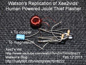
This is my replication of Xee2vids’ Human Powered Joule Thief (Flasher), in a Youtube video.  The changes I made are as follows.  I used a BC550C which is the same as the BC547C very common NPN transistor.  I thought that since the flash rate looked too fast on the Youtube video, and since a slower flash rate would give more power and a brighter LED per flash, that I would choose a resistor that was higher than the original 100k. I used a 390k, but I found that the flash rate was too slow, so I put a second 390k resistor in parallel.  That gives about 200k, and the flash rate is about 1 per  second at 1.5V.

Instead of a white LED, I used a blue-green or aqua LED like the ones used in traffic lights.  Instead of a 1 inch toroid core, I used a small (ICH) YJ41003TC toroid from surplussales.com.  I wound two lengths of 24 inches (60cm) of 30 AWG (0.25mm) enameled wire onto it, bifilar wound.

The current is very low and  the light output is very low, even though I’m using a superbright LED.  The current drain must be in the few tens or hundreds of microamps.  But that is all  this human powered battery can supply so it should be a good load match.  I went over at lunchtime to Big 5 Sporting Goods and bought the magnesium fire lighter for ten bucks.  I also got two five pound barbell weights on sale for four bucks each.  I’m going to use them for the base of my table lamps.

I was thinking of soldering a few pennies together to make the copper electrode.  But I think I’ll wait until I get home and try to come up with something better, probably a small piece of copper clad PC board.   I can’t remember if I have a short piece of  copper pipe.  I know I have some relatively large diameter 1.25″ copper pipe, but it’s sixty bucks for ten feet, and I would have to saw off four or five inches, which is not easy when it’s that big.

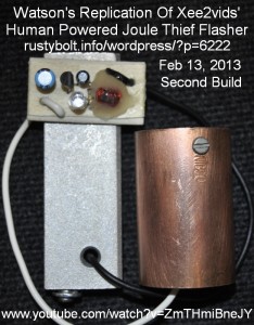
I got home this evening and decided that I wanted to make this project complete by mounting all of the parts on a piece of birch plywood, the same as I used in the projects in the last few blogs.  I wound a new coil, using an (ICH)T231212T core from surplussales.com.  I used two 11 inch lengths of 32 AWG solid enameled wire bifilar wound.  The inductance was about 660 uH. I held it down to the board with some hot glue.

The transistor was again the BD550C, the resistor was 180k, and the LED was again the aqua or blue-green superbright LED.  I used short lengths of 18 AWG power cord wire to connect the magnesium fire starter block and the copper coupling to the board.  All together it worked well, and looked a lot better than the earlier air wired prototype.

I looked around for toroids on eBay and found quite a few but they were all expensive.  It seems that nowadays you can’t find anything up for bid – it’s all buy it now, no negotiating.  So I google searched for toroids and found a lot, but they all seem to be websites for brokers, you have to submit a RFQ, request for quote.   If I can’t buy them for a given price, I am not going to wait for some turkey salesdroid to get back to me and try to gouge me for all I’m worth.  I’ve tried to go to some manufacturers to get a list of distributors, but most don’t want to deal with you if you buy anything less than a couple thousand on tape and reel.  That narrows it down to some of my favorites: Mouser, Arrow, Newark, Futurlec, Digikey, etc.  maybe I’ll check Goldmine Electronics too.

default

2013-02-11 Germanium ETCO 2N652 Joule Thief

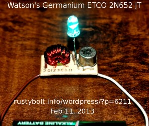
I need more germanium JTs to run down the AA cells to less than a tenth of a volt, so I put this one together using an antique germanium 2N652 made by ETCO.  I used a blue-green or aqua LED like the ones used in the traffic lights.  It uses a Fair-Rite 2643002402 core.  The core has about 18 inches (49 cm) of 30 AWG (.25mm) enameled wire quadrifilar wound with three of the four conductors connected in parallel for the primary winding.  The resistor is the customary 1k. The 2N652 is PNP, therefore the negative or brown wire on the left goes to the coil, and the white wire goes to the emitter of the transistor and LED.  The LED is “backwards”, the cathode or flat spot goes to the collector and coil winding, and the anode goes to the emitter and positive (white) wire.

As can be seen, the LED is very bright.  I used the piece of birch plywood that’s similar to the ones I used the last few days for the flashers.  That gives the circuit a solid mounting surface just like a PC board.  I didn’t think there was any point in measuring the current at 1.5V because these germanium JTs will for the most part be used on cells that are half dead and under 1 volt and constantly decreasing…  Lower, and lower, until the dead cell measures 0.1V or less.

default

2013-02-10 Nuclear’s Model T

I was reading an article in the ASME “mechanical engineering” magazine called “Nuclear’s Model T”, which talked about building small nuclear power plants in a factory and shipping them to their operational sites.  This issue was Vol.131/No.7 July 2009.  The article was published a few years before the Fukushima Daiichi disaster.

First off, I will state flatly that I have nothing against nuclear power.  However there are some points that the average person should understand before making any intelligent decision pro or con.

At this time, Feb 2013, nuclear power seems to be dying in the U.S..  The Japanese have shut down almost all of their 54 nuclear power plants and since they require the citizenry to give permission to restart the plants and there is so much bad sentiment after Fukushima, it looks like they may never restart them.

After Fukushima, the Germans have now decided to shut down all of their nuclear power plants in the next several years.  They believe that renewable power should replace nuclear power.

There is a single nuclear power plant being built in the U.S. but it is the only one in decades that has gone through the planning and building stages.  Others have been cancelled.

After Fukushima, it is unlikely that any IOU (investor owned utility) will build a new nuclear power plant.  I think a number of factors will prevent it.  One is that the investors will not want to invest the large sums of money needed to build one.  And then there is getting an insurer to insure one.  Most likely the insurance premiums will be exhorbitant.

I think the biggest obstacle will be the public.  NIMBY or not in my back yard!  No one will want to live near one and will not allow one to be built, especially after the Fukushima disaster (the Shoreham Nuclear Power Plant is just one example).

The San Onofre Nuclear Generating Station, one unit has been shut down recently due to cracks in the pipes.  This was just rebuilt and they seem to have been unable to get it right.  Now how much faith in nuclear power do you have when the rebuilders can’t even rebuild the power plant?

It’s always nice to know that we have shot ourselves in the foot when it comes to nuclear power.  There is plenty of solar, wind, tidal and geothermal energy out there waiting to be harvested, so why don’t we get with the program, like Germany has, and build a lot more solar photovoltaic plants?  We can do it.  We have the best locations for PVs in our southwestern deserts.  Someday these nuclear power plants are going to have to be shut down, so why not be ready for the future?  I think there is too much procrastination with renewable energy.  More solar and wind power should be built, until there is enough to supply most of the power.  In order to get the solar and wind power to be better prepared for variability in the sun and wind, we need to expand the national electrical transmission grid.  Then some bad weather in one part of the country will not have such a bad effect.


default

2013-02-09 Flashers Bowden Style

I have built several of the “Single Cell Flasher With Two Year Battery Life” flashers found at Pigeonsnest.co.uk and they flash for what seems like eternity – they’re real misers when it comes to battery current.  But the flash is somewhat anemic and I had never tried this type flasher with any color LED other than red.  When I saw Bill Bowden’s similar flasher, I decided to try building one to see how well it worked.  The Pigeonsnest flasher used 10k and 27k resistors to supply current to the LED part, so I figured that since Bowden’s flasher uses 330 ohm resistors, it would be much brighter.  I was happy with giving up the long battery lifetime of the Pigeonsnest flasher to get a brighter LED flash.

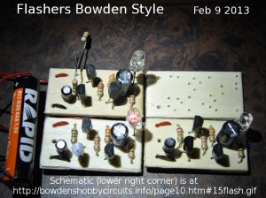
For my first attempt at building one I used a 3/4 inch by 1-1/2 inch piece of birch plywood that I got from Michaels crafts/hobby store.  They’re about 0.08 inch (2mm) thick and come in a bag of assorted sizes for $4 or $5.  I made the holes with a small drill in a pin vise turned by hand.  The wood is thin and easy to work with.  Assembly was easy.  In the picture, I show my first build in the upper left corner, the second in the lower left, a third build lower right and the blank board.

I followed the schematic with two changes.  Instead of 1k, I used 1.1k, which was just ten percent higher so it should not make any difference,  I used a S8050 NPN high current transistor for the LED driver transistor, in place of the 2N3904.  I thought that this would be an improvement, given that the Pigeonsnest flasher recommends that this transistor should be a high current transistor.  The other two transistors were as shown in the schematic.

Performance Of First Build

I finished the assembly and connected it to a fresh AAA cell.  I observed a few sporadic flashes, but it refused to flash steadily.  I double checked the wiring to make sure it conformed to the schematic.  I checked a few points.  I tried a 22k resistor across the base to emitter junction of the S8050, but it would still not flash steadily.  I have built and experimented with many of Bowden’s circuits and I know that the circuits shown on that website have met Bowden’s expectations, one of which is that they are good working designs.  So I wasn’t sure what the problem was with my first build.  It could be a bad part or it could be that one of the changes I made had adversely affected the circuit.  I decided that I should give up on this one for now and try another one and get it working.

Performance Of Second Build

I got the parts together and two blank boards.  I used the exact parts, no changes or substitutions, even though I think the 2N3904 is not the best choice for the driver transistor.  I also used a red high brightness LED.  I clamped two boards together, one on  top of the other with a spring clamp.  I had the first build as a pattern so I eyeballed where the parts were to go and drilled both boards at the same time.  This way, I can build one of the boards and keep the other as a pattern.  I assembled the second board – everything went together smoothly, and soldered the red and black wires on.  I connected it up to a AAA cell, and it worked.  The flash rate was a bit on the fast side – 10 flashes in 7 to 8 seconds.

I connected it up to a power supply along with a 100 ohm resistor in series with the positive lead and 60 thousand microfarads of capacitors across the red and black leads.  This filtered out the current spikes caused by the flashing, and at 1.5V, my DMM measured 115 millivolts across the 100 ohm, which equals 1.15 milliamps average  current.

Thinking and Sorting It Out

Now I have two flashers, one that’s dysfunctional and one that’s working fine.  The one that works has the exact parts that are shown in the schematic.  The non-working one has some different parts, but in my judgment the differences should not cause it to stop working.  I needed to prove that I could make changes to the working one that would make it like the non-working one but without causing it to stop working.  But instead of making changes, I decided to build the third one with the changes, to see if it would work.  I examined the schematic and believed it was a valid design, and that those changes would not stop it from working.  Onward.

The Third one

I had planned ahead and made the third board so it was quick and easy to stuff it with the parts.  Just like the second except I included some changes,  One was the driver transistor: I used a 2N4401 – it’s capable of higher current.  I decided to use a yellow LED, which has a higher forward voltage, but should not have an effect on its operation.  Since the second one flashed faster than what I wanted, I changed the 1.5 meg to 2.2 meg.  This third flasher went together quickly and powered up with bright yellow flashes without a problem.

Back to the problem

By now I was convinced that the reason for the dysfunction was not in the changes I had made.  I had three of them working, and I decided to try fixing the first one.  I changed the output transistor from the S8050 to a BC338, which wasn’t much of a change.  Not a help; it still flashed sporadically.  I replaced the 2N3906 with another 2N3906, but it still flashed sporadically or not at all.  Feb 10 morning…  I replaced the first (left most) 2N3904 with another 2N3904.  Wow.  It started to flash regularly without the sporadic problem.  I think I fixed it, but I don’t understand why the original 2N3904 was not working.  I’m using new parts, never before used.  They should not be defective.  I suspect that the circuit is sensitive to some parameter that varies from part to part.  This may be the gain or leakage of the first transistor.

I decided that it would be a good idea to coat the boards with some clear acrylic spray.  I tried to get the spray can to spray, but apparently it had been sitting on the shelf for so many years that the propellant slowly leaked until it would no longer spray.  Instead I gave two of the boards a coating of clear nail hardener, something I got at the dollar store and was still liquid enough to brush on.

While they were drying I decided to change the 2.2 Meg resistor to 1.8 meg.  This was board #3, which was flashing at about 10 flashes every 12 seconds.  I wanted it to be about 1 second per flash, so I unsoldered the 2.2 Meg and put a 1.8 Meg in its place.  I powered it up and it was acting just like the first one: sporadic flashes once in awhile, maybe ten seconds or more.  This third build was working okay before.  Something  in the circuit design seems to be causing this instability.

The Leakage Problem

I thought about it, and the one thing I had not replaced before was the 1 uF electrolytic capacitor.  Lytics tend to be more leaky, and in this case I was not sure if the polarity was correctly shown in the schematic.  I decided to solve both by replacing the electrolytic with a 1 uF ceramic capacitor.  That didn’t help the problem at all.

One other concern I thought might be occurring was the leakage problem again.  The first transistor’s collector is connected directly into the second transistor, which is connected directly into the third transistor.  If each of the transistors has a current gain of 200, then the total gains is 200 times 200 times 200.  Just 200 times 200 is 40 thousand, which is so much that when a hundredth of a microamp (10 nanoamps) of leakage leaks into the base of the first transistor, it gets amplified up to nearly a half milliamp (0.00000001A times 40000 = 0.0004A or 0.4 mA).  But this has three transistors, each with a gain of maybe 200.  So 200 times 200 times 200 is 8 Million!  Even a thousandth of a microamp gets amplified up to 8 milliamps!  To bleed some of that leakage away, I put a 10k resistor from the base to emitter of the 2N3906 PNP transistor (second transistor from the left).  That was enough to stop the leakage current from the first transistor from being amplified by the second and third transistors.  And 10k is high enough to not be a problem when the transistors are switched on during the flash.  But it did have one slight effect: with the 1.5 Meg resistor the flash rate was a bit high, about 10 flashes every ten seconds, and with the 10k resistor added, the flash rate slowed down to about ten flashes every 10 to 12 seconds.  That was closer to what I wanted.

Now that I had found the Achilles Heel of this circuit, I drilled holes in the other boards and put the 10k resistors on them, too.  They all slowed down a bit.  I changed one of the resistors from 1.8 Meg to 1.3 Meg and it flashed just about exactly once a second.

The 10k value is just a convenient one; any value from a few k up to 100k may do the job.  There was one last thing that I wanted to add: a daylight sensor to turn off the blinking during the daytime.  I thought about using a CdS photocell from the base to emitter of the first transistor.  The problem was that the 1.5 Meg resistor supplies so tiny a current to the base that a CdS photocell would shunt most of it away even in a dark room.  Instead, I used the same circuit that I added to my Blue Blinky.  I connected an LED between the base and emitter of a PN2222A transistor.  I then connected the emitter to the negative and the collector to the base of the first transistor.  The tiny current generated by light on the LSD (light sensing diode) is enough to turn on the transistor and shunt the 1.5 Meg’s current to negative.  This simple circuit is not very sensitive; it will allow the board to blink in normal light, but when the LSD is held close to a bright light or outside in daylight, the blinking is stopped.  With the Blue Blinky, I changed the PN2222A to a BC547C, which has higher gain and will turn off the blinking in a normally lit room.

Conclusion to end of confusion

I now have four stable boards that brightly blink a red, orange or yellow LED down to about 1 volt, with no signs of instability.  This circuit is now brighter and better than the Pigeonsnest circuit.  I have added the daylight sensor, which is doubling the battery life.  If I had my old desktop running, I could have designed a PC board with ExpressPCB and submitted it to the company to get PC boards made.  But I haven’t had it running for months, and I’m not sure if it will start up after sitting so long.  I have backups, but I can’t do any designing with ExpressPCB since I’m running Linux, not Windoze.  But I still have my Blue Blinky PC boards, which work with any color LED.

I uploaded a short Youtube video of a comparison of the Pigeonsnest 1.5V flasher on the left with the modified Bowden’s flasher on the right.  It’s obvious which is brighter.

One change that can be made is to replace the lower 330 ohm resistor with a diode, cathode to negative.  I can’t guesstimate what the benefits are, but it’s better than the resistor as long as the cell voltage is 1.5V or less.  If the cell voltage were to increase, the LED and diode would both be forward biased and excessive current would flow, with possible overheating and damage.A 1N4148 regular diode would work, but a 1N5817 Schottky diode would be best.

I built the Supercharged Joule Thief Flasher, which is simpler than this one but has some disadvantages.  The SJT Flasher will run to a lower voltage, but will not turn off, it just stops flashing and glows dimly and uses up the battery.  The Bowden’s Modified Flasher will flash down to about 1 volt, but when it gets too dim to flash, it stops and doesn’t draw any more current.  That allows you to remove the cell and use it in a regular Joule Thief.

I have found that Bowden’s circuit is similar to the one found here (scroll down to the bottom).  It looks like the leakage problem there was solved by the 100 ohm resistor.  Note that the LM3909 circuit to the left of it has long been out of production and unavailable for many years.  Here is another site that has Bowden’s circuit.  Notice that except for the watermark “freeciruitdiagram.com”, it is identical to Bowden’s schematic.  From what I’ve seen on this site, it looks like they have stolen schematics from other websites and use them with adverts to make money.  Perhaps Jobs was right. (I emailed Bowden with the change I made.)  However after the having the above leakage problems, I would say that anyone who attempts to build it will have the same problem I had.  This should be a lesson to the plagiarists.  When they steal someone’s schematics, they eliminate the possibility of getting it updated when a correction is made to the original.  If they had linked to it, any changes would be in theirs, also.

Update Feb 16 – I put the Pigeonsnest flasher on a power supply along with a 1k resistor in series and 40 thousand microfarads of capacitors.  That averaged out the pulsing current, and I measured the average supply current at under 50 microamps at 1.5V.  No wonder the AA cell lasts for years!  As I said I’ve built several of them, and the circuit is a good design (compared to the above).  But it does need a serious injection of LED current to make it brighter.  Instead of 50 microamps, the cell current could be 200 to 250 microamps, and the cell would last for many months.

For more modifications on this flasher, see my 2013-02-17 blog.  Back to experimenting…

default

2013-02-07 Battery End Of Lifetime

I have read the claims of many Joule Thief fanatics who say that the JT will “suck the life out of dead batteries” and that’s how it got its name.  But by the time the Joule Thief gets to a battery, isn’t it already mostly used up?

During the Xmas holidays and since then, I have been connecting dozens of AA cells up to Joule Thiefs and putting them on a shelf.  I’ve run down these supposedly dead AA cells to well below a quarter of a volt, due to my use of germanium transistors in the JTs.  I also use silicon JTs, but they can only run the AA cells down to 0.4 volts or so, leaving enough ‘juice’ in the battery to run the germanium JTs.  But I have observed that the cells having less than a half volt when connected to germanium JTs have very little life left in them; they run for a short time before they drop to less than 0.2V.  I’ve watched some die a minute or two after I connect them.   I’ll admit that many of these dead cells have been lying around for quite awhile.  But even the recently dead cells with around 1.3 volts last only a few days on the shelf, and even then, they quickly dim so that much of the JT’s light output is only in the first few hours, with much lower light output while dimming down later.

Comparing these dead ones to a fresh cell is quite a difference.  The fresh cell lasts a lot longer and the LED is at full brightness (see note).  My point is that the almost dead cell has but a small fraction of its charge left, most of it being used up in the toy or camera from which it was discarded.    I think that the JTers who tout how much life is left in these dead cells really haven’t looked at the overall scene.  If they really want to get all the energy from those AA and AAA cells, they should do it with fresh ones, thereby saving the extra weight of carrying around a bunch of nearly dead cells.

I put some cardboard on the shelf before I put the JTs on the shelf.  I have several blobs of dried battery juice on the cardboard, where the cells leaked and then dried.  Without the cardboard I think the shelf would have had the paint damaged by the juice.  One day I thought it would be a terrific idea to spread several dozen JTs out on the floor, each lit up by its own dying AA cell.  Then I could claim the World Record for the number of Joule Thiefs running at one time.  But then my sensibility took over and I remembered that I might damage the floor with battery juice, so I didn’t do it.

Back to juicing…

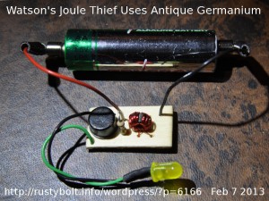
Note:  One has to realize that the Joule Thief circuit has a difficult time driving the LED to full brightness (20 mA) from a fresh 1.5V cell. When the voltage drops as the cell dies, the JT has an even harder time to boost the voltage up to the LED’s 3.3V.  This is why  the LED dims so much as the cell dies.  It is also why the cell takes so long to die: the current drain gets lower and lower as the voltage drops, which prolongs the slow cell death.  When the cell is below 1V, the LED really begins to dim and soon is no longer able to furnish enough light to do any illumination.  It just indicates that the circuit is still running.  Just like the LED in the picture.  The germanium Joule Thief is sucking the last few hundred millivolts out of a dead AA cell.  The yellow LED is just barely glowing, hard to see when the lights are bright.

default

2013-02-06 Coil And Crystal Tester

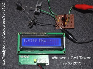
I had already built one of these several years ago, and since I’ve used it to test the crystals that I’ve salvaged.  It’s a simple circuit, using only a single transistor to make a Colpitts Oscillator with the two leads for the inductor run to terminals so that various inductors and coils can be connected up for testing.  The circuit I built years ago had a rectifier and second transistor to drive a LED to show that the crystal was oscillating.  In the one I built yesterday, Feb 5, there is only the single transistor for the Colpitts Oscillator. There are two capacitors connected in series, from the base to negative common.  The top lead of the top capacitor is connected directly to the base.   The bottom lead of the toip capacitor and the top lead of the bottom capacitor are connected together and to the emitter of the transistor.  The bottom lead of the bottom capacitor is connected to negative common.  I used two 470 pF capacitors; the values equal.  But I see other schematics where the top capacitor is much larger value compared to the bottom capacitor.


Using The Circuit

I connected the output of the oscillator to a frequency counter so I can compare various coils to see what frequency they oscillate when combined with the internal capacitance of the circuit.  In this case, the two capacitors are in series and when combined total 470 pF divided by two, or 235 pF.  There is about another 10 pF stray capacitance in the transistor and wiring, making the total about 245 pF.  What I liked about this circuit is that when I combine the 245 pF with a 100 uH coil, the resulting resonant frequency is almost exactly 1 MHz.  I thought that was very interesting.  Right in the middle of the AM broadcast band.  I put the 100 uH choke on the circuit and the frequency meter can be seen reading about 34 kHz higher than 1 MHz.  This allows me to estimate the frequency fairly accurately by tuning an AM radio to the frequency and then estimating the frequency by comparing it to the other adjacent radio stations on the dial.  In this case, when the oscillator is turned off, I could hear another radio station at 1020 and 1070 on the dial, so I knew the oscillator was about halfway in between.  Once I know the approximate frequency, and that the combined capacitance of the oscillator is 245 pF, I can use the resonance calculator (choose one from this search) to find the inductance of the coil.

Alternately, I can use the frequency of the radio to tell if my toroid coil is higher or lower than 100 uH, and add or subtract turns to adjust it to about 100 uH.  It doesn’t have to be exact, but if the frequency is higher or lower than about 1100 or 900, some turns should be added or subtracted.

When I looked at the waveform on the scope, it was distorted on the top.  I suspect this was because the capacitors were the same value, instead of being unequal as seen in many other schematics.  Some schematics show the upper capacitor as being ten times  the value of the lower capacitor.

The reason I used the 470 pF capacitors is that they are 1 percent silver mica, and are very accurate and don’t change with temperature.  I calculated that I could use six of these capacitors and get 1410 pF (three in parallel) for the upper capacitor, and 313 pF for the lower capacitor (three caps, two in series with a third one across either of the others).  This would give me an equivalent of 256 pF for all of the capacitors.  The ratio is not ten to one, but it is much better than the equal values and it is close to the original 245 pF.

Update Feb 6 afternoon – I changed the capacitors to the six as explained above.  The waveform is still distorted, but maybe not as much as before (I don’t have a way to directly compare them).  The distorted waveform becomes less distorted when the supply voltage is below 2 volts (the circuit oscillated down to 1.6V).  The frequency is lower, it measured 938 kHz.   But the frequency is sensitive to what is connected to the output.  When I connected the scope probe, the frequency dropped well below 900 kHz.  I suspect the frequency counter is also causing it to drop.  I disconnected everything from the output and found the frequency on the AM radio.  I found out the frequency of the station it is next to: 980.  The circuit is oscillating at about 970 kHz with a 100 uH inductor.  According to my calculations, it was supposed to be at 977 kHz, so the actual frequency agrees closely with the calculated frequency.

One way to reduce the frequency sensitivity, I believe, is to take the output from a tap on the emitter load resistor.  Another way is to put another transistor on the output to act as a buffer stage.  If the coil tester is used with an AM radio and no load on the output, then nothing would have to be done.

Additional Circuits

I was considering adding buffer if needed, a rectifier and filter to the output.  The reason for this is to make a frequency sensitive DC output.  The DC output would vary with the frequency, so that for example if the coil tester was oscillating at 938 kHz, the output might be 0.938 volt (the output would be read with a DMM).  This would not be as accurate as listening to the radio, but it should be good enough to give a good idea of the frequency, and thus the value of the coil.  For right now, I’m happy to be able to find the frequency with the AM radio, and confirm that the inductor is about 100 uH.

default

2013-02-05 LEDs In Parallel

If you open up a cheapo 9 LED flashlight you will find that they put 9 LEDs all on the same PC board and they are all connected in parallel.  How do they do this without having the LEDs burn out?  For decades, the engineers have warned us that you should never connect LEDs in parallel, because of unequal current distribution.  Also, one LED starts to hog the current because its forward voltage is lower than the others, so it gets hotter.  Then as it gets hotter, the forward voltage decreases, so it hogs more current, and so on until the LED is damaged by the excessive current and heat.

If so, then how do the 9 LED flashlight makers manage to do it and not have these problems?  I have a couple theories as to why they can do it and it doesn’t damage the LEDs.  One is that the LEDs all come from the same maker and have a forward voltage that may not be matched, but they are close enough so that the current is fairly evenly distributed.  Another reason is that all of the LEDs are mounted close together on the same PC board, and if one gets hotter than the others, its heat is distributed to the other LEDs, so they start to draw more current, too.  This evens out the current draw somewhat.

I drive down the streets and stop at many stop signals that have the red and green lights made out of LEDs.  I see many of them that have a section of the LEDs that are not working, or that flash on and off intermittently.  This leads me to believe that the large arrays of LEDs are getting too hot and damage is the result.  So I don’t think that putting a lot of LEDs close together is such a good idea.

There are LED makers that mount several LED chips onto the same frame inside of the LED.  The frame is metal and distributes the heat well so that if one LED chip gets a little hotter, its heat is spread out to the other chips.  These multichip LEDs may have very high power – up to 30 watts.

Does this mean you can build a multi LED project and connect all of the LEDs in parallel?  I would not do it unless I knew for certain that all of the LEDs are from the same maker and are from the same batch, so their forward voltages are very close.  Instead I would give each LED its own current limiting resistor and eliminate any possibility that the LEDs could be damaged by excessive current and heat.

I have put several LEDs in parallel on Joule Thiefs.  I think that the high current pulses cause a voltage drop across the LED’s internal resistance.  This causes the current to be distributed more evenly over all the LEDs.

default

2013-02-04 Joule Thief Efficiency Versus Base Resistor

Paul posed a question about the base resistor and how it affects efficiency.  This is a point that was apparently addressed by the low Vce(sat), high gain transistors that were made especially for DC to DC converters.  Since the BJT (bipolar junction transistor) is a current operated device, the current that it needs to turn fully on is a fraction of the total power and if it can be minimized, it will help increase the circuit’s efficiency.

The graphs for the BC337 and similar transistors show a graph of collector current versus the Vce(sat).  Typically in the corner there is text that says “Ic / Ib = 10″ or something similar.  This means that the base current, which is normally 1/100 or less times the collector current, has been forced to 1/10 of the collector current in order to drive the transistor out of the linear region and into saturation.  The saturation measurements are made at this ratio.

But in the datasheet for transistors that are made for high current switching, the graph may say “Ic / Ib = 30″ or even a higher ratio.  I assume that the transistor has such a high gain and low Vce(sat) that forcing the base current down to 1/10 of the collector current has no more benefit than forcing it down to 1/30.

What I see is that with the BC337, the base current is ten percent of the collector current and is using up to ten percent of the total power.  But in the case of the special transistors, the current is only 3.33 percent of the total, and wastes 1/3 as much power as the BC337.  The less power is wasted, the greater the efficiency.

What is also important is that during saturation the special transistor takes much less to get the voltage drop to less than a quarter volt, and in some cases less than a tenth of a volt.  This gives as much of the energy as possible to the coil, since almost all of the battery voltage is across the primary winding.

Some of the special transistors are:

2SD965 – Panasonic – for an example see page 2 of the .PDF datasheet here.

2SC2500D – Toshiba – for an example see page 3 of the .PDF datasheet here.

2SD5041 or KSD5041 – Fairchild – see page 2 of the .PDF datasheet here.

ZTX651 – Zetex – .PDF here

ZTX1048A – Zetex – .PDF here

NTE11 – NTE nteinc.com

There are several more that are older and no longer used, and there are several common ones that are in surface mount packages.  All of the above are for through hole mounting, typically in the TO-92 package.

default

2013-02-02 Faster Joule Thief – Flagiusz Version

My “rival” Flagiusz has done some experimenting with a version of a Joule Thief which uses a capacitor similar to my Supercharged Joule thief, but is simpler.  He also claimed that it was a bit more efficient than my SJT.  This version, which he calls Fast Joule Thief, is the second one after the ‘basic’ or conventional Joule Thief.

I built one up according to the schematic on his website.  In the schematic he showed the inductances of the coil windings as being 10 uH but he did not give any specifications for the toroid core.  I used a low permeability core, and bifilar wound about 18 inches (460mm) of 24 AWG (0.5mm) solid insulated telephone wire on the core.  This gave me 22 uH per winding.   My reason for a higher value winding is that the lower value might cause the frequency to go so high that it would interfere with the AM broadcast band.  I used the BC337-40 as shown in the schematic.  I used the 5.6k resistor as shown in the schematic.  I used the 680 pF capacitor as shown in the schematic.  I used a white LED as shown in the schematic.  He did not show a 22 uF bypass capacitor across the power supply, so I did not use one, however the power supply has a bypass capacitor internally.  I used a 1.0 ohm resistor in series with the cathode lead of the LED to monitor the LED current.

My first build gave the following results.

Vsupply = 1.50V, I supply = 92 mA,  F=202kHz, Iled = 27.8 mA,  Efficiency = 66.5%

Vsupply = 1.278V, I supply = 78 mA, Iled = 20.0 mA  Efficiency = 56.1%

These are not much better than the conventional JT, especially in the case of the lower supply voltage.

Update Feb 3 – “If You Build It, They’ll Come”

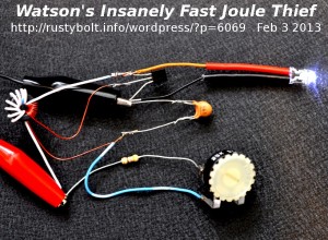
Since the results for the first Fast Joule Thief were much less than spectacular, I decided to start with a new one, completely from scratch with all new parts.  The result is what is seen in the photo.  I still have to add a 1 ohm resistor to the LED’s cathode to monitor the current.  As shown, the transistor is a BC337-40 as called for in the schematic.  The LED is a Nichia NSPW500BS as called for in the schematic.  The toroid is a high mu core wound with two separate windings, each 9 turns of wire, each having an inductance of 220 uH.  The capacitor was a 560 pF in parallel with another cap to make a total of 680 pF.  The resistor was a 25k trimpot in series with 470 ohm current limiting resistor.  At 1.5V supply voltage and 80 mA supply current the resistance was adjusted to 6.5k.

I powered it up and the LED lit up, but not very brightly, at least for a brand new Nichia NSPW500BS.  I adjusted the trimpot to get about 80 mA current with the supply voltage set for 1.5V.  Well, I figured I should measure the frequency, but my freq meter said zero even though it was connected across the LED.  That’s not right, the LED is putting out light.  So I fired up the o’scope and connected it up.  I turned the sweep speed down to a half microsecond per division, but the sine waves were still tiny and blurry.  I counted thirteen cycles per two divisions, and that calculated to 13 MHz.  WHAT?!?!?!?!?  That’s insane!  This crazy JT is running faster than any JT I’ve ever built!  I built a five MHz JT, but this is ridiculous!  Something is not right here.

While I was editing the photo, I noticed the windings on the coil.  They were not making sense, so I looked at the coil, and I think I goofed.  Whew!  That had me going crazy for awhile.  I was thinking that Flagiusz was going to get me in trouble with the FCC for not having a radio amateur’s license when I’m working on his FJT.  I switched the wires of the feedback winding and now it’s running at 53 kHz, a much more sane JT frequency.

I added the 1 ohm resistor in series with the cathode of the LED.  I powered it up, and put a DMM across the 1 ohm res.  I also connected the scope probe and found that the peak current pulses through the resistor were almost a quarter of an amp.  The DMM averaged them out, and showed about 15 mA.  I adjusted the trimpot, but as soon as I got the DMM up to 18.6 mV, the LED would go out if I tried to go above 18.6 mA.  I disconnected it and measured the total resistance and it was 1010 ohms.

Vsupp = 1.5V  Isupp = 92 mA   f = 48 kHz.

Iled = 18.6 mA   Rtot = 1.0k  Efficiency = 44 percent.

That’s a really mediocre efficiency, the same as a ‘basic’ or conventional JT.

© RustyBolt.Info/wordpress
CyberChimps