default

2013-02-24 Simplest and Worst Flasher Circuit Ever

This weekend I did something I thought I really would never do – I already knew that this circuit was a loser.  The guy has a web page with “the simplest LED flasher”, which uses an NPN transistor with the base disconnected and the emitter positive which is supposed to break down at less than 12V.  This is a ‘negative resistance’ which causes the capacitor to discharge and flash the LED.  This uses the transistor in a way that it was never meant to be used.  I think it’s an unacceptable design – I’ve never seen this used in any commercial product or hobby kit.  But I decided to try it with three different transistors.

I built the circuit as shown in the diagram, but I used a 470 uF capacitor.  One of the transistors let the LED stay on all the time.  The second one – a PN2222A – flashed, like it was supposed to.  The  third one did nothing, even when I turned the voltage up to 30 volts. Only one out of three attempts worked, which is not an acceptable success rate.

But the last one really had me puzzled.  I subjected the transistor to up to 31 volts yet it did not break down, and that is not normal – almost all of the transistors should breakdown a few volts above their 5 or 6 volt maximum emitter to base breakdown voltage rating.  This transistor is one I recently purchased, a run-of-the-mill transistor, the 2N3904.  What did they do to it to make the thing so immune to breakdown?  If all the newer transistors are like that, this circuit would never flash (see note below).

The transistor that let the LED stay on constantly was behaving like a zener diode.  When the voltage reached a certain point, the transistor broke down and started to conduct, and let the current through to the LED, which to my thinking is normal.  It’s just like a zener diode.

The transistor that flashed was exhibiting the negative resistance that let the voltage build up, then discharge through the LED.  I varied the voltage from below 11 volts up to 12V and the flash rate was speeding up faster as it approached 12V.  The circuit is very sensitive to voltage, but will the next transistor cause the circuit to be sensitive to a different voltage range?  Or will the circuit just not work, like two of the three I built.  It’s best to avoid this circuit and not slip into the pitfalls of a really bad design.

Note:  I’m really puzzled about this, and wondering if the transistor chips are being made with state-of-the-art stuff like those found in more advanced chips.  It’d make sense if the chip fab plant used the higher tech stuff to make transistors such as the 2N3904 transistor that I tested.  This transistor was a simple design first made by Motorola in the early to mid 1960s. Any transistor maker can make a 2N3904 if it meets the minimum specifications in the datasheet.  But there’s nothing from stopping the maker from far exceeding those specifications.

Think about this.  A transistor could have some extra “enhancements” built into the silicon that is not a part of the actual transistor.  This could monitor the temperature. for example, and shut the transistor down if the temperature exceeded a safe margin.  Or if you want to get really paranoid, it could monitor the data, looking for secret messages, such as “Bin Laden” or similar.  Just kidding, but the silicon could really add some safety features to the transistor.  Better not tell anyone, though.  It’s a s-e-c-r-e-t.  😉

default

2013-02-23 PC Boards Cheaper

I commented on a Youtube video and the author replied he found that he could get PC Boards made for cheap from Futurlec.com.   I looked at their FAQ and found that they will accept designs made in ExpressPCB, which is what I use.  Their cost estimator said I can get the same boards for 44 dollars, 2/3 the cost of expressPCB’s $66.00.  And single-sided is even cheaper.  I can also get them made single-sided with the silk screen for even a little cheaper.  There is no minimum but the setup charges are fixed, so it pays to order enough boards to reduce the total cost per  board (not including setup, mine are $1.27 each).

I have sent a few of my designs to ExpressPCB.  One of them, my Blue Blinky, is my favorite.  I’ve built at least 25 of them so far, but I think I won’t be ordering any from Futurlec because I still have four boards that I haven’t stuffed with parts.

Once I ordered some boards for my”Fading Red Eyes” which is a ‘PSO’ phase shift oscillator that runs at about 1/3 Hz.  It drives six LEDs, and needs about 6 to 9 volts., depending on the color of the LED.  It’s a simple circuit so I could build it on the plywood boards I’ve been using lately.

My recent projects, the flashers, might be a candidate for some boards from Futurlec.  However, I’ve built 6 or 7 of the Bowden flashers, and I think I’ve about had as much fun with it as I can stand.  The dual switched capacitor board might be a good candidate, since it will drive any color LED.  It has about 21 components, not including the AA cell.  I could put it on a long thin board like my Blue Blinky and then use the same paper clip loops for the battery holder.  The original one I built is 1 inch by 1-3/8 inch (25mm by 35mm) so I think it would fit nicely on the same size board as my Blue Blinky.

Having the PC board also serve as the battery holder is very convenient and helpful, but if the circuit is very low power, as is the case with these flashers, then it may be better to design the holder for the AAA cell.  Or could I make a battery holder out of paper clip loops that would hold both AA and AAA cells?  I’ll have to think about that.

default

2013-02-22 Fastest Joule Thief In The World? Slowest?

What is the fastest Joule Thief in the world?  I have had one operating at 13 MHz, believe it or not.  What is the slowest Joule Thief?  I built one with a large coil, and the high inductance caused it to operate at 1200 Hz, well within the audio frequency range.  I think that that is the slowest Joule Thief I’ve had operating, however it’s relatively easy to get one to go slower.  It’s more difficult to get it to run at very high speed.

In the case of the 13 MHz JT, I had one of the windings connected backwards, so it was 180 degrees out of phase and theoretically it should not have done anything.  But it took off at 13 MHz instead, and even put out light from the LED.  It was a real screamer.  The fastest JT I have had with the windings correctly connected was 2.5 MHz, with very few turns on the air core coil.  I suppose I could have removed more turns and made it run even higher.  But as the frequency increases, the losses increase until the JT is wasting most of the power and gives very little light.  It’s better to run the JT at a frequency where the losses are a small fraction of the total losses.

Back to experimenting…

default

2013-02-20 EnCAPsulated ‘Joule Thief’ V Booster

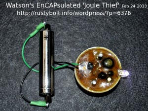
There are many other uses for common household items, or even stuff that would otherwise go to the trash or recycling.  In this case, I built a two transistor “Joule Thief” V Booster on a small perf board, put it inside of a soda bottle cap along with two screws and encapsulated it in epoxy – that’s why it’s enCAPsulated.  The photo shows the choke with a single winding, labeled ‘104’ for 100 microhenrys.  The epoxy has turned a bit dark with age.  I use the term ‘Joule Thief’ but it’s not a true Joule Thief.

This circuit uses two transistors because I built it back in the early 2000s (might have been  Oct 2003) before I had learned how to get a single transistor to put out enough current to light the LED to full brightness, or about 20 milliamps.  Instead, I used the conventional two transistor circuit and a choke with a single low resistance winding.  I had only had limited experience with winding toroids, and I didn’t have enough experience to know what kind of core to use or how to wind it with heavier low resistance wire.  I remember the chokes cost about a dollar apiece.  Nowadays, I can wind a toroid core with two short lengths of telephone wire for about 12 cents.

The two screws were to anchor it down in an outside environment; the epoxy was for protection against the weather.  Later I found that the transistor has to be capable of handling very high current at low voltage, and that meant the transistor has to be chosen for that purpose – many transistors are not capable.  The wisdom of Joule Thief building came to me after a few years, and I learned from experimenting and experience that if I wanted to see good Joule Thief performance, I had to understand how they worked and what to use for components.  I guess I could call it the Care and Feeding of Joule Thiefs.   I thought about authoring a book, which would consist mostly of the  blogs I had written about Joule Thiefs in my late watsonseblog.  But it went away, thanks to the BOFHs at blogger.

But back to this circuit.  The LED is very bright and can be seen even though the camera’s flash is very bright.  I built several of these same circuits, and put them in Velamints tins (a  miniature Altoids tin).  One of them can be seen in my blog here.

Back to experimenting…

default

2013-02-19 Watsonseblog: Copper Saver “Joule Thief”

The following is from my late Watsonseblog dated 2010 Dec 26 (no pics or links yet).

I made this a few years ago when I tried to see how well these two transistor JT type circuits work, and how efficient they are.  The coil is a 180 microhenry RF choke with a single winding, and a DC resistance of about 2 ohms, which is not good enough for efficiency.  It would be better if it was well under 1 ohm.  The inductance value could be lower, 100 uH would have lower DC resistance.  The circuit is one that is commonly found at websites and in projects.  Performance was about the same as a regular single transistor JT.

As I said in the pic, it saves copper by eliminating the feedback winding and replacing it with a 3 cent transistor.  Silicon is cheaper than copper, but it takes very little wire to wind the feedback winding on a coil.  So I’m not sure if this saves money.  One thing about coils is they have to be either wound by hand or by machine, and it takes longer to assemble than a capacitor or transistor.  Since wire is subject to breaking and/or shorts, the failure rate is most likely greater than for other components.  And throwing silicon at a circuit has been the norm for the last fifty years – it’s nothing new.  And one advantage is that cheap RF chokes can be bought for about 30 cents apiece (Mouser 580-11R104C).  The toroid with two windings is no longer needed, but can still be used.

For the experimenter (or the the newbie or experimenter who’s lazy or wants to throw it together quickly and have it work), the plus side is that there is no concern about how many turns of wire and of what gauge are needed for the feedback winding, or what’s the ratio between the primary and feedback winding.  However, the circuit is a bit more complex than the conventional JT.  If you’re winding a toroid, the lack of the feedback winding gives you more room to wind more turns of the primary (or only) winding, or even better yet, you can use heavier wire and still get the same number of turns on the core.

One minus is that the  gain of the two transistors is multiplied, and transistors typically have a large gain spread, so if you have selected two high gain transistors or two low gain transistors, the value of Q1 base bias resistor R1 may be too low or too high.   That’s why I show two resistors in series.  The single resistor was on the side of being too low, so I added the second resistor to optimize it a bit.

It would be a good idea to put a potentiometer in there temporarily and vary the resistance over a range to see what seems to be best.  Then remove the pot, measure it, and put in a regular resistor close to that value.  This is done so the performance of the circuit can be observed while you vary the supply voltage, for example.  If the resistance is too low or high, you might have the circuit quit when the voltage gets out of range.  We all know that the battery’s voltage will drop as it gets depleted, so you want the circuit to still work when the voltage drops so you can suck the last joule out of it, just like a vampire.*

Performance

This circuit is essentially the same circuit that was used in a flasher, with the capacitor reduced from a few microfarads to a half a nanofarad.  The light is replaced by the coil, and the LED is added across the output transistor.  Here is a schematic of a similar flasher circuit.

The performance was better than I expected since I figured  the extra transistor would use some of the current and waste it as heat.  But the circuit takes about the same amount of supply current and puts out about the same current to the LED as a single transistor Joule Thief.  That’s about 80 milliamps supply current, and 17 milliamps LED current, which is measured across the 1 ohm resistor; every millivolt is equal to a milliamp.

Silicon Saver Joule Thief

This Joule Tief is a conventional one: the transistor, the resistor, and the coil.  But it’s unique in that it has no silicon at all.  Instead, it uses germanium, quite uncommon in transistors today, but the only thing that was used in  the early days, the 1950s and early 1960s.  The coil is an EMI/RFI suppressor sleeve from a keyboard cord or whatever.  A dozen turns of 24 AWG solid telephone wire make up the windings.  I used a 390 ohm low value resistor so that it would be bright at low battery voltages.  I think that if I were to put it on a fresh battery, it would draw excessive current and overheat.  The pic shows it operating easily at 0.274 volts from the battery.

I received an email with some good advice from Jack, of muzique.com.  With his permission, I’ll quote below.

Just a word about germanium transistors.  You cannot usually measure the HFE of a Ge device with a DMM because of leakage that is very common with these vintage transistors.

For example, take one of your vintage PNP germaniums, and connect the emitter to +9V and the collector to a 2.2k resistor then to battery negative.  Let the base float free.  Since the base is not being biased by a current, there should be no voltage flowing through the transistor, but if you connect your DMM across the 2k2 resistor, you will probably find a small voltage and this is caused by the leakage.

The current leak will cause the DMM to read a falsely high value for the HFE.

I would guess that the leakage is the source of most of your problems with getting Ge-JTs to work.  You could select one with a very low leakage and see if that helps.

I have a Peak Electronics transistor tster that can measure germanium leakage and derive a correct hfe value.  This is a fast way to sort old transistors.

Also, the hfe and leakage will vary with temperature, as you have probably noted. Germaniums are much more sensitive to heat than silicon devices, and this might reduce their potential for JT use.

Best regards, Jack

Thank you, Jack.

default

2013-02-18 Watson’s Blinky Booster Flashes Blue LEDs

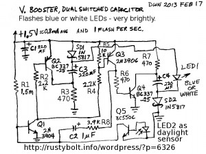
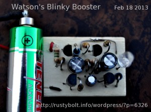
I named this “Blinky Booster” dual switched capacitor voltage boost flasher after my Blue Blinky, which used a coil.  This dual switched capacitor voltage boost flasher uses no coil or inductor.  Last week I got Bowden’s flasher, a single switched capacitor voltage boost flasher, working properly, but it was not capable of flashing blue or white LEDs.  The dual switched capacitors put twice as much voltage boost out to the LED, so it’s capable of flashing white or blue LEDs.  Bowden’s flasher used resistors to supply current to the switched capacitor, this one uses two Schottky diodes to block the reverse current when the capacitors are switched.  These two 1N5817 Schottky diodes are a lot more expensive than two resistors, but they help reduce losses and improve the performance.  If cost is a factor, the resistors could be used instead.  It might be possible to use the 1N4148 cheapo diodes, but I haven’t tried it yet.

Why Not A Joule Thief?

What are the advantages and disadvantages of this circuit compared to a Joule Thief?  It’s hard to beat the simplicity of a Joule Thief – it’s obvious from looking at the schematic that this is more complex- four or five times as many parts.  It’s probably more costly, too, but that depends on how much the JT coil costs.  That is one advantage: it doesn’t use a coil, so no coil to wind, or to try to obtain already wound.  Another advantage is that since it doesn’t use a coil, there are no electromagnetic fields generated so electromagnetic interference and radio frequency interference are minimal if not absent.  Another advantage is that this circuit uses the R1 and C2 to control the pulse frequency, and R8 to control the pulse width.  This allows those to be adjusted with little interaction.  The Joule Thief is so simple that the pulse width and frequency are ‘intertwingled’, where trying to change one makes the other change.

Another disadvantage is that the voltage boost depends on the supply, so the flash dims rapidly when the battery voltage drops down to 1 volt and is completely gone below 0.9V.  But the very low current drain – 0.8 milliamps average – means that it will take a long time to deplete a fresh cell; probably months.  I’m not sure what the capacity of an alkaline AA cell is, but if it is 2000 mA-h, then the cell should last for 2500 hours, which is close to 15 weeks.  But that’s running 24/7; if the daylight sensor turns it off half the time, then it will be close to 30 weeks or more than 6 months.

That’s another point about this circuit: the daylight sensor.  It uses any color LED (red is probably cheaper) as a daylight sensor.  The LED’s feeble current is amplified by Q5 which shunts the current from the 1.5 meg to negative.  It would not be possible to use a CdS photocell or LDR here because the smallest amount of light on it would reduce its resistance to much less than the 1.5 Megohm resistor.  But the LED aka LSD and Q5 work just fine.  When the whole circuit is turned off, there is minimal current draw from the battery.  I have not yet added the daylight sensor to the circuit because I anticipated that the circuit would need a lot of work (the Bowden circuit took a lot of my time), so I wanted solve any problems before adding the daylight sensor later.  But to test it, I shorted the base of Q1 to the emitter, and the supply current was less than 1.5 microamps; that amounts to the current through R1 and no current in the rest of the circuit.  And 1.5 microamps is essentially no load to the battery so it will last its shelf life.  I have not tried to add a daylight sensor to the Joule Thief flasher, but it would add several more parts to the circuit.

The bottom line here is: Would I use this circuit instead of a Joule Thief Flasher?  If the low battery current, long cell life and bright flash of a blue or white LED were the higher priority, then the answer would be yes.  Otherwise, the simplicity, and cheapness of the Joule Thief Flasher would be a better choice.

Update Feb 21 – I built a second circuit.  I used the first one above as the template and eyeballed the locations of the holes on the blank board and drilled the holes.  I clamped two blanks together and drilled both at the same time, so I have a third board to use either as another circuit, or else as the master template to drill more boards.  On the first board, I had a few tight places because it was the ‘prototype’ board; I couldn’t foresee what was going where.  On these second and third boards, the components will be more properly positioned, knowing what I know after building the first board.

I powered this second board up, and it flashed erratically and a bit fast.  I measured the voltage on the board and it was dropping down the below 1.35 volts.  The contacts on the battery were apparently causing the problem.  When I removed one of the magnets, its end was covered with green corrosion.  I scraped it off and the erratic fast flash disappeared.  When the flasher draws heavy current during the on time, it puts a high current demand on the cell.  If there’s just a slight amount of resistance in the contacts or wiring, it shows up as a drop in cell voltage.  Clean contacts and good soldering joints take care of the problem.

Back to experimenting…

default

2013-02-17 Flashers Bowden Style (Continued)

This is a continuation of the earlier blog.  I wanted to change two parameters, the flash rate and the peak LED current.  To do these, I experimented with the following.

Flash Rate

I built a sixth one (or seventh – I’m beginning to lose track, even though I labeled them).  I changed the C1 capacitor from 1 uF to 0.1 uF.  I tried it, but the flash rate was a bit too rapid.  So I drilled two holes next to the 0.1 uF and soldered a 0.22 uF cap in parallel.  The total was then about 0.32 uF, and  the flash rate slowed down to just a bit less than 3 per second.  This was about where I wanted the flash rate to be.  R1 was 1.5 Meg, but I could have increased it to slow down the flash rate.  I’ve used up to 2 Meg so far with no problems.

LED Current

When I pulled the parts, I changed R3 and R4 from 330 to 120 ohms.  The flashes were going to be faster, so there was effectively less current per flash, given that C2 was the same value.  So in order to charge up C2 faster, I chose 120 ohms.

When I reduced the R3 and R4, the Q2 switching transistor was now handling more current.  So first off I used a BC338, which I know from experiments handles high Joule Thief currents very well.  Then I tried a second BC338 in parallel with the first, and it seemed brighter, so I drilled three holes next to the original transistor and soldered the BC338 in parallel permanently with the original.

Results

The results look good.  The flash rate is about 3 per second and the flash is very bright.  I thought about lifting the base of the second BC338 and giving it its own 1k resistor, so the two transistors were not sharing the current from the original 1k.  This would double the base current and cause both transistors to be even more saturated, with less voltage drop from collector to emitter.  I was thinking that the amount of improvement would be several hundredths to a few tenths of a volt, which isn’t very much, so I haven’t done it yet.  I think I’ll first try adding a second 1k in parallel with the first, to see if it helps.  Maybe I can look at the collector voltage with the o’scope and see if there is any difference.  I may try some heavier duty transistors such as the SS8050 or maybe the ZTX1048A that I purchased recently.  I have a few other ideas that I may try to implement.  One of these is to switch R4 to a 1N5817 Schottky diode.  The one problem I see is that with resistors, I could change the battery to two cells, especially two 1.2V Ni-MH rechargeable cells.  But if the diode is there, the higher voltage would cause the LED and diode to conduct heavy current with overheating and possible damage.

Another flasher

I found a similar flasher on TE, but it uses only two transistors.  Scroll down to the figure that says “1.5V LED Flasher circuit-2”.  This gives similar performance to the Bowden’s Flasher, but it uses only two transistors.  Fewer transistors means less gain and better stability.  I’ve built a few of these and the flash is very bright, and there is no problem with the stability.  I measured the average current and it was about a half milliamp, which is ten times higher than the Pigeonsnest.co.uk flasher, but a bit less than the Bowden flasher.  This is a point where there is a good compromise between the flash brightness and the battery lifetime, which should be many months.  After comparing this circuit with the flasher from Bowden, I would say that since this one is simpler and shows no sign of instability, I would recommend it over the Bowden flasher to the experimenter who wants something to work right off the bench.

Update Apr 13 – I checked the schematic on Bowden’s Hobby Circuits website and it still hasn’t been changed.   I still haven’t heard from Mr. Bowden and it’s been more than a month.

Back to experimenting…

default

2013-02-16 Eco Wave Power’s Medium Scale Wave Energy Power Plant

Ya know, 10 kilowatts isn’t bad for a couple of floats bobbing up and down in the ocean (Youtube video).  But like anything else, it will probably meet strong opposition from those that think it’s an eyesore or disturbs the environment.  Actually I have a strong suspicion that a lot of the anti-whatevers use environmental concerns as a way to prevent or get rid of such renewable energy sources.  Maybe they own a lot of stock in the petroleum and fossil fuel companies, and are worried that the fossil fuels will get replaced by renewable energy.  I certainly hope so, for the planet’s sake.

default

2013-02-15 Cell Phone Charger, Auto Type

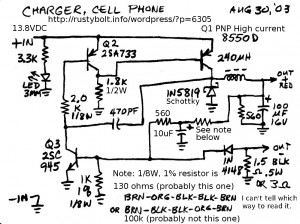
I drew this schematic almost ten years ago, and of course the actual charger is nowhere to be found.  I think it may have burned out somehow, and that was why I drew the schematic.  Whatever the case, it does have current limiting, which has to be in anything like this that might be used by the consumer.  The resistor in the note was so small that it was not possible to tell which way the bands were supposed to be read.  I didn’t think of measuring it, however it might have been damaged.  The 8550 is a very common transistor in consumer type electronics.  It could be replaced by a BC327-25 but I don’t know if this substitute would give as much current.  Maybe a better replacement would be a BD136.

Another thing I don’t remember anything about is the choke.  It says 240 uH but I don’t remember if it was an axial or radial choke or toroid (probably not – they’re too expensive) or what the DC resistance was.  I believe the whole circuit fit inside of a cigarette lighter plug, so the PC board had to be small, and so did the choke.  There would also be a 1/4 amp fuse built into the plug.

Update 2014 Jan 2 – I was thinking about the resistor with 5 bands.  This resistor along with the other resistors should divide the voltage so that when the output reaches 5V, the base voltage on the 2SC945 gets to .6V and starts limiting the output voltage.  If the resistor was 130 ohms, it would be too low, and 100k ohms would be  too high for this to happen, I believe.  So the best solution that I can think of is to temporarily replace it with a 10k pot, and adjust it for the 5V output.  Then remove the pot and replace it with a resistor of the same value.  By the way, these chargers typically use a thin gauge wire in the cable, so it’s a good idea to have the output a few tenths of a volt above 5V, to compensate for the V drop in the wires.

default

2013-02-14 Tiny Inverter Transformer From Goldmine-elec.com

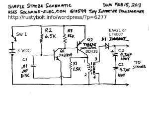
I received the bag of these tiny inverter transformers that I ordered from goldmine-elec.com.  Each was tiny: 10.7mm wide, 10mm deep, and 9mm high, not counting the leads.  There are two windings, the primary which is 0.11 ohms and an unknown inductance, and the secondary which is 48.4 ohms and 350 mH.

They sent a single page along with the pinout and a schematic of a strobe using this transformer.  I redrew the schematic since it was oddly drawn, and I’m going to make some modifications to it.  They made some fundamental mistakes that I’m going to correct.  The first mistake was to use a TIP126 Darlington transistor for the driver transistor (my earlier blog explains why).  The supply is only three volts, and .6 volts of that is wasted across the TIP126, as heat – that’s 20 percent!.  The first thing to do is get rid of the Darlington.  I’m changing it to a BD438 PNP transistor.  I will also change the 2N3904 to a PN2222A.  Then I have some doubts about the values of R2 and R3.  R2 is low for the bias resistor for a small transistor.

R3 doesn’t seem necessary because the TIP126 has built-in resistors across the base to emitters of both transistors.  But since I’m changing it to a BD438, I think it could be lower.  It has passed through my thoughts more than once that it looks like the values for R2 and R3 may have been switched.  But the 6.5k looks like it should have been 5.6k.  I think R3 could be 1k and not waste much power.

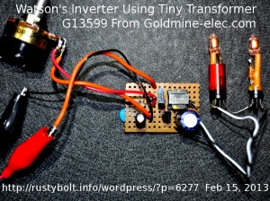
I have changed the R2 to a 10k in series with a 100k pot.  I adjusted it to about 10k, so the total R2 is about 20k.   I changed the C1 capacitor from .005 uF to .001 uF.  That blue capacitor can be seen peeking out from under the circuit board.

The BAV21 or UF4007 is just to reduce the losses from slow reverse recovery of the 1N4007.  The C2 and C3 capacitors need 1 meg or 470k resistors to bleed off the high voltage when the circuit is not operating.  Also, the resistors would equalize the voltages across C2 and C3.  But I am not going to use two capacitors in series, I will use a single 10 uF capacitor, rated at 350 volts.

I connected two NE-2 pilot lamps in series and connected them across the output as a load.  Each lamp has a 33k resistor in series with it.  I measured the voltage drop across one 33k at 14 volts, so the current through them is 0.42 milliamps.  As can be seen, they light up brightly.  The supply current at 3 V was about 200 milliamps.

Back to experimenting…

Update – I used this transformer in my blog about the “Joule Thief” that is powered by a 40 millivolt thermocouple.

© RustyBolt.Info/wordpress
CyberChimps