My “rival” Flagiusz has done some experimenting with a version of a Joule Thief which uses a capacitor similar to my Supercharged Joule thief, but is simpler. He also claimed that it was a bit more efficient than my SJT. This version, which he calls Fast Joule Thief, is the second one after the ‘basic’ or conventional Joule Thief.
I built one up according to the schematic on his website. In the schematic he showed the inductances of the coil windings as being 10 uH but he did not give any specifications for the toroid core. I used a low permeability core, and bifilar wound about 18 inches (460mm) of 24 AWG (0.5mm) solid insulated telephone wire on the core. This gave me 22 uH per winding. My reason for a higher value winding is that the lower value might cause the frequency to go so high that it would interfere with the AM broadcast band. I used the BC337-40 as shown in the schematic. I used the 5.6k resistor as shown in the schematic. I used the 680 pF capacitor as shown in the schematic. I used a white LED as shown in the schematic. He did not show a 22 uF bypass capacitor across the power supply, so I did not use one, however the power supply has a bypass capacitor internally. I used a 1.0 ohm resistor in series with the cathode lead of the LED to monitor the LED current.
My first build gave the following results.
Vsupply = 1.50V, I supply = 92 mA, F=202kHz, Iled = 27.8 mA, Efficiency = 66.5%
Vsupply = 1.278V, I supply = 78 mA, Iled = 20.0 mA Efficiency = 56.1%
These are not much better than the conventional JT, especially in the case of the lower supply voltage.
Update Feb 3 – “If You Build It, They’ll Come”
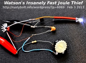
 Since the results for the first Fast Joule Thief were much less than spectacular, I decided to start with a new one, completely from scratch with all new parts. The result is what is seen in the photo. I still have to add a 1 ohm resistor to the LED’s cathode to monitor the current. As shown, the transistor is a BC337-40 as called for in the schematic. The LED is a Nichia NSPW500BS as called for in the schematic. The toroid is a high mu core wound with two separate windings, each 9 turns of wire, each having an inductance of 220 uH. The capacitor was a 560 pF in parallel with another cap to make a total of 680 pF. The resistor was a 25k trimpot in series with 470 ohm current limiting resistor. At 1.5V supply voltage and 80 mA supply current the resistance was adjusted to 6.5k.
I powered it up and the LED lit up, but not very brightly, at least for a brand new Nichia NSPW500BS. I adjusted the trimpot to get about 80 mA current with the supply voltage set for 1.5V. Well, I figured I should measure the frequency, but my freq meter said zero even though it was connected across the LED. That’s not right, the LED is putting out light. So I fired up the o’scope and connected it up. I turned the sweep speed down to a half microsecond per division, but the sine waves were still tiny and blurry. I counted thirteen cycles per two divisions, and that calculated to 13 MHz. WHAT?!?!?!?!? That’s insane! This crazy JT is running faster than any JT I’ve ever built! I built a five MHz JT, but this is ridiculous! Something is not right here.
While I was editing the photo, I noticed the windings on the coil. They were not making sense, so I looked at the coil, and I think I goofed. Whew! That had me going crazy for awhile. I was thinking that Flagiusz was going to get me in trouble with the FCC for not having a radio amateur’s license when I’m working on his FJT. I switched the wires of the feedback winding and now it’s running at 53 kHz, a much more sane JT frequency.
I added the 1 ohm resistor in series with the cathode of the LED. I powered it up, and put a DMM across the 1 ohm res. I also connected the scope probe and found that the peak current pulses through the resistor were almost a quarter of an amp. The DMM averaged them out, and showed about 15 mA. I adjusted the trimpot, but as soon as I got the DMM up to 18.6 mV, the LED would go out if I tried to go above 18.6 mA. I disconnected it and measured the total resistance and it was 1010 ohms.
Vsupp = 1.5V Isupp = 92 mA f = 48 kHz.
Iled = 18.6 mA Rtot = 1.0k Efficiency = 44 percent.
That’s a really mediocre efficiency, the same as a ‘basic’ or conventional JT.