default

2013-02-01 Lithium Battery Is Overkill For Joule Thiefs

I measured the voltage of an unused Energizer Lithium AA cell, and found that it was 1.806 VDC, and another one measured 1.807V.  Wow!  Looked like the Energizer Bunny was running on jet fuel!  These are very potent batteries.  Their voltage is 20 percent higher than the normal AA cell.  These lithium cells are supposed to have a very long 15 year shelf life, so they make good choices for emergency flashlights.  I got these with some bargain bin stuff, so they didn’t cost very much, but normally they’re very expensive – over 3 dollars for a single cell,   I started to think about the ramifications of using these in certain circuits, especially Joule Thiefs.

There are certain circuits that are sensitive to excessive supply voltage.  Take for instance the flasher at Bill Bowden’s Hobby Circuits website.  The red LED is in series with a 1k resistor, and both are connected directly across the battery.  If the forward voltage of the red LED is 1.8V, it will light up constantly when connected to a 1.8V lithium cell, and soon deplete the cell.  The 1k resistor will limit the current, so nothing will happen to the circuit, but there could be a n expensive but dead lithium cell very soon.  Red LEDs vary in their forward voltage; some of the ones I have need closer to 2V to be at full brightness, but might light up at 1.8V.

This also applies to the Joule Thief, but to a greater degree.  The LED is connected directly across the battery – through the coil winding, but that is very low resistance.  If the LED is red, it could light up without the transistor’s help.  Most JTs use an LED with a voltage higher than 1.8V, so this shouldn’t be a problem.

But due to the Joule Thief’s high sensitivity to voltage variations, the 1.8V cell will cause the LED current to be much higher than usual.  This could be excessive for the LED, but the biggest problem will be the short life of the 1.8V cell.  The JT will suck it dry much sooner than an alkaline cell.

Save your money and get the cheaper batteries.

default

2013-01-31 Emitter To Base Breakdown in a Joule Thief

I left a comment to one Joule Thief experimenter (video is on Youtube) that one should never power a Joule Thief with no LED connected.  If the emitter to base voltage exceeds the breakdown voltage the resulting current will permanently damage the transistor by reducing the current gain.  He tried running the Joule Thief with no LED for hours and he said the results were that it did not harm the transistor.

Here is what I know.  When there is no LED, the emitter to base voltage is the same as the collector voltage, only the opposite polarity, because the windings are 1:1 ratio. When the transistor switches off, the voltage between the emitter and base will climb as high as it can until the emitter to base junction breaks down.  Then current will flow through the emitter to base junction.  There seems to be some misunderstanding in the above statements so I’ll try to explain it simply.

The transistor switches off, and the voltage across the base to emitter climbs along with the collector voltage.  Because there is no current flow through the emitter to base, there is also no current flowing through the resistor and there is no voltage drop across the resistor; all of the voltage appears across the emitter to base junction and since the winding ratio is 1:1, the voltage follows the collector voltage.  When the voltage climbs to the breakdown voltage of the emitter to base junction, it starts to conduct and the resulting current flow causes any further voltage increase to appear across the resistor.  The emitter to base junction acts like a zener diode.  And the current through the emitter to base junction is what damages it.

My Tests

First I measured the transistor’s gain – may have been about 300.  The transistor I tested was not in a Joule Thief, but in a test fixture with enough DC voltage to cause the emitter to base junction to break down.  This was typically above 6 or 7 V but less than 10V.  I had a current limiting resistor in series with the emitter to base junction.  I increased the voltage until the current limiting resistor had a few volts across it, indicating that there was current flowing through the resistor and through the emitter to base junction.  I let the current flow for a few minutes.  The transistor dissipated very little power, only ten or so milliwatts during this time.  Then I removed the transistor and checked the current gain, and found that it was much lower, 100 or so.  And this was permanent, I tested the gain later and found the same low current gain.

I cannot explain why the experimenter’s Joule Thief circuit seems to not be affected by running it with no LED.  If the voltage is exceeding the emitter to base breakdown voltage and there is current flowing backward through the emitter to base junction, then it should damage it just like if it was in my test fixture.

I’ll have to try the test with various transistors to see if the current gains are affected by breakdown of the emitter to base junction. BRB.

Actual Transistor Tests

Update – I tested three transistors.  I put a 3.3k resistor in series with the emitter to base junction and then connected t to a power supply. I connected my DMM across the resistor to monitor the voltage drop.  I turned up the voltage, and at about 8 or 9V, the meter started to show the voltage drop.  I turned up the voltage until there was about 3.3V across the resistor, which meant there was 1 mA flowing through the breaking down emitter to base junction.  I then let this current flow for two more minutes.

I first tested a BC550C which is the same as a BC547C except it is low noise. The starting current gain was 575.  The ending current gain was 535 and the loss was 40.  That’s about a 7.5 percent loss.

I then tested a PN2222A.  The starting current gain was 188.  The ending current gain was 171 and the loss was 17.  That’s about a ten percent loss over just two minutes.

I then tested a BC338.  The starting current gain was 315.  The ending current gain was 291 and the loss was 24.  That’s about a 7.5 percent loss over just two minutes.

I believe in all 3 cases if I had used a higher current and/or a longer time the damage would have been worse.  In  all 3 cases if the voltage rose above 8 or 9 volts, the junction would start to break down.

Applying This To The Joule Thief

So far I have not proved that any of this applies to the Joule Thief.  What I have proved is that all three of these common transistors will be permanently damaged in their current gain when their emitter to base junction is subjected to current flow when the emitter to base junction is in breakdown.

When the Joule Thief is powered with no LED, the emitter to base junction is exposed to voltages in excess of its emitter to base breakdown voltage.  Does this damage the transistor, like it did in my tests?  I will have to test a few transistors to see if it does.

My Test Results In A Joule Thief

Update – I put a socket on a Joule Thief so I can insert and remove transistors without soldering.  I also added a switch to the LED so I can disconnect it from the circuit.  The coil has a bifilar winding with a 1:1 ratio.  The resistor is 1000 ohms.  I connected my scope probe across the emitter to base junction to see the negative voltage with and without the LED connected.  I’ll call this my test jig.

I measured the current gain of a PN2222A at 175 before the test.  I inserted it into the test jig with the LED connected, and saw negative spikes on the scope that were about 2 volts peak.  The LED glowed brightly.  I disconnected the LED and the scope showed the negative spikes had increased to a negative 9 volts peak, which is about where a typical transistor’s emitter to base junction breaks down.  I let it run for a few minutes, then I shut it off.

I removed the transistor and measured the current gain and it was 151, which was 24 less than before the test.  The current gain had dropped about 14 percent.  I then put the same PN2222A back into the test jig and watched the negative spikes again go to 9 volts peak.  I let it run for a few minutes and again measured the current gain, and it went down to 146.  Not as much drop as the first time, but this still shows that the transistor was permanently damaged the second time, just like the first time.

This confirms what I said at the beginning regarding running a Joule Thief with no LED.  If I had continued to run the transistor in the test jig with the LED disconnected, the current gain would continue to decrease.  Eventually the current gain would be too low for the circuit to operate.  This is just a matter of time and as I said, the damage is permanent.

Update Feb 1 – I measured the gain of a BC550C at 515.  I put it in the test jig and ran it with no LED for ten minutes.  I removed it and measured the gain and it was 480.  It had lost 35 or 6.8 percent.  I put it back into the test jig and left it running. I will come back in a much longer length of time and measure it.  It’s been more than an hour, and I measured the gain, and it is down to 445.  I’m going to leave it running overnight.

Update Feb 2 – the next morning, about 7 hours later, I measured the current gain of this transistor at  428.  I put it back in the JT with the LED off, to see how much more abuse it will take and how low it will go.  The frequency with LED was 24 kHz, with no LED was 38 kHz.  At noon, I measured the current gain at 423.  The breakdown damage seems to have leveled off with only a small amount of change every few hours.


default

2013-01-30 IR Remote Emulator Learns and Sends

I’ve thought about this a number of times in the recent past.  There used to be a .ZIP file on the ‘netcalled Xanadu Zapper which consisted of plans and code to implement an IR xmit/recv interface for the PC along with code for learning and sending the IR codes.  Many years ago I built the interface (just a IR LED connected the the parallel printer port) but my TV was an old one with a weird remote so it would not work.

I decided that I would try another trick many years ago.  Since my TV’s remote was weird, I decided that the remote extender project that I had found would not work.  This project used a Sharp GP1U52X IR receiver to receive and demodulate the remote’s pulses, and then retransmit it again, I think it used a 555 timer chip.  I thought that why would you want to receive and demodulate the code and then go to all this  trouble to remodulate again, when all you really need to do is just receive the carrier, amplify it and then resend it again.  If I point my weird TV remote at it, it does the job, no problem whether it’s weird or not.  If I point my VCR remote at it, it does the job, no problem.  DUH!!!

So I built a preamplifier and IR LED driver and mounted it along with the IR phototransistor in another room and ran a twisted pair out to a point in front of the TV and VCR and connected the IR LED to it.  Then when I brought my remote into the other room, I had  complete control of the TV, VCR, or whatever.

Today, the remotes are good, but you can’t be in another room and point the remote anywhere with the hope that it will conttrol the TV or whatever.  I moved into a bigger place and now it’s not so practical to just run a pair of wires from one room, down the hallway, over the kitchen counter and to the TV ,VCR, DVR, etc.  I really miss my old remote extender; it made things a lot easier when I was moving from one room to the other.

I think it would be possible to implement such a device by receiving the IR remote carrier signal, amplifying it and then modulating it onto a radio frequency, which will only be transmitted briefly when the IR signal is being sent.  I would call this an extender.  There could be more than one of these extenders, each in its own room.  The receiver would be a low sensitivity receiver that is broadly tuned to the frequency so that it could receive the various extenders without problems.  Since only one frequency would need to be used, the receiver could be a TRF, or tuned radio frequency receiver.  The channel bandwidth would have to be wide enough to accommodate the remotes, which have a carrier frequency around 38 kHz.

This system would not have to be sophisticated, it would not need microcontrollers.  I was thinking that the best frequency to use would be one of the vacant TV channels in the area, such as ch. 7 or 8.  This is high enough to allow a small antenna, but low enough to be transmitted and received by common transistors.

default

2013-01-29 Low Voltage Joule Thief Ch. 3

Paul discussed some points regarding the low voltage joule thief.

(I’ll have to get his permission to put the paragraph here.)

First I have to admit that I’m not an expert when it comes to electromagnetics and toroid cores and transformers.  The reference data books give standard information such as the transformer’s voltage step-up is equal to the ratio of the turns.  Great, but the stuff about B-H curves and the like is a bit out of my league.  I’ve read about this but I don’t claim to understand it well enough to make accurate judgments regarding cores, etc.  That said…

I tell people that the Joule Thief uses a coil, but it doesn’t transform.  The output of the JT is taken from the same winding as the input, and the second feedback winding is there only to keep the circuit oscillating and is not needed for the actual DC to DC conversion.

However in the case of the low voltage JT, the output is not taken from the same winding, it is taken from the same feedback winding that’s connected to the gate of the JFET.  So the transformer terminology may apply in this case.

The JFET is not like a transistor which requires input current to get output current.  The JFET requires a change in input voltage to get a change in output voltage, like a vacuum tube or valve.  Also, with zero voltage on the gate, the JFET is already conducting current.  To get the JFET to switch off requires a negative voltage on the gate to turn it off.  The JFET operates differently than a regular transistor, which I will call a  BJT, short for bipolar junction transistor.

Back to the coil.  In order to get enough voltage to switch the gate with a supply of a hundred or less millivolts, the ratio of the primary and feedback windings has to be very high.  I used 2 turns on the primary and 400 turns on the feedback winding in my low V JT.  That brought the overall gain up to where the Low V JT would oscillate at well under a hundred millivolts.

But the others who were experimenting used a 2SK170, which could operate below 30 millivolts.  The objective was to get the LED to light with the heat from a human body.  But if you want the LED to light up bright enough to illuminate something, it will take several tens of milliwatts of power, and at 30 millivolts, that’s much more than 1 amp of supply current.  The 2SK170 is only capable of a few milliamps, so it will not come even close to making the LED bright enough to illuminate anything.

Paul said that one could not get much work done from a 40 millivolt thermocouple, but the thermocouple is generating enough power (many amps?) to energize a solenoid and hold the armature in against the spring pressure of a few ounces.  And it does this as long as the pilot light is lit in the gas heater or  water heater.  The problem is just getting that very low voltage, very high current stepped up to enough voltage to be useful in lighting an LED or running a microcontroller, etc.  And that’s what we are trying to do.

I’ve used a MOSFET to step up 0.7 volt at more than 1 amp to enough power to drive a high power LED.  So I figure that it can be done at an even lower voltage.

Remember one important point: In a JT, increasing the number of amps at the sacrifice of inductance is better because the energy stored is equal to the current squared.  Increasing the number of turns stores more energy, but the decreasing current is also squared, so you lose more.

default

2013-01-28 Joule Thief Efficiency Versus Supply Current

Paul asked a question:

If you increase the resistor and the [supply] intake current reduces, what does the efficiency do?

Paul has asked several questions about Joule Thiefs that I had not thought about previously, and they’ve brought up some thoughts that may be important and should be examined further.

I have calculated the efficiency of a Joule Thief, but I haven’t done a graph with points for supply current versus efficiency for a certain combination of transistor, coil, etc., and I would expect that the info would only apply to that particular JT, not to others.  I’m speculating about this, but since the current is less, the Vce(sat) will be lower, and the loss across the transistor will be less.  Also the gain will be a bit higher, so it should help lower the power wasted on the base bias.  But there may be other factors that I haven’t considered that may influence the results, such as core losses and frequency changes.

default

2013-01-27 Tiny Aqua Joule Thief Uses CFL Core

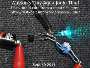
This is a photo of a Joule Thief I built more than a year ago using the core from a dead CFL light bulb.  The windings were only 9 turns each of solid insulated telephone wire.  That was all I could get on the core.  This core is the typical size for the CFLs where there is limited space in the base of the light.  I’ve seen smaller ones, too.  They all seem to be high permeability so that it does not take a lot of turns to get enough inductance (100 uH or more) for a Joule Thief.

default

2013-01-26 DC-DC Converter 1.5V To 9V

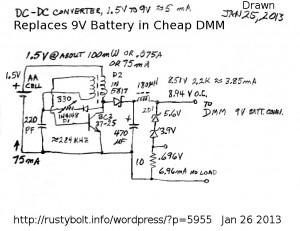
I’ve been trying to get a stable 5 milliamps of current from this circuit, which is a Supercharged Joule Thief with the LED replaced with a rectifier, filter capacitor and zener shunt regulator.  I’m getting about 9V with no load, but when I put a 2.2k load resistor on I get 8.5V which is drawing about 3.8 milliamps.  I think 4 or 5 mA would be enough to run the DMM.  The total current through the ZD1 is about 7 milliamps no load, so if the voltage drop doesn’t cause the DMM to complain, then this circuit might be able to fulfill its job of replacing the 9V battery.  One other thing: it should have a bypass capacitor across the battery – 220 uF or more.

The circuit is not efficient overall because the output is shunt regulated.  The Zener diodes just waste the excess that isn’t being used.  But the inverter “Joule Thief” part of the circuit is efficient because it’s a Supercharged Joule Thief,  This keeps the total current drawn from the battery down to 75 milliamps.  If it was a conventional JT, the current would be over 100 mA.  Since the DMM is used only intermittently, I figure that the single AA cell should last more than a dozen hours, which is weeks even in my extreme case of using the DMM every day.  I could have used two AA rechargeable cells, which would be about 2.5V, and just keep trickle charging them when they’re not in use,  I should experiment with another one that is optimized for 2.5V.

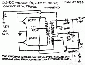
I built a circuit in April, 2007 which used two transistors to drive the output.  This lightened the current load for each transistor.  The two push-pull transistors balanced the DC in the core and the center tapped output winding had two diodes for full wave rectification.  I don’t remember whether or not the feedback regulated the output well or not.  The blog I wrote about it went away along with that information when watsonseblog was removed.

I think there could be a few improvements.  There should he a bypass capacitor from the center tap of the feedback (bottom) winding to ground.  The 47 uF capacitor could be larger, 220 uF or more.  The BC338 should be changed to BC337-25 to give a bit more balance to the two transistors.  The 8.2k and 1k resistors should be higher, maybe 22k and 2.7k, to minimize wasted power.  It might be a good idea to change the 2.7k to a 2.2k and 1k pot to allow adjustment of the output voltage.

default

2013-01-25 What Defines A Joule Thief?

In this Youtube video comment, he asks the question

[A] Joule Thief is a concept or it defines a device that uses a toroid?

About your Q:   The original Joule Thief was a simple one transistor device that used the inductive kick or Counter EMF of a coil to boost a low voltage up to the voltage needed to light the LED.  The coil originally was a toroid, but it can be a bobbin, bar or rod of Ferrite, or it can be a coil of wire with an air core, or any other non-magnetic core such as a piece of wood or plastic.  This original “Conventional Joule Thief” used a 1.5V battery, a single transistor, a single resistor, and a coil and LED.  A bypass capacitor of 10 or more uF across the battery wasn’t in the original but is optional and recommended as it helps stabilize the circuit when the battery is weak.  Anything more  complex than this is not a  true Conventional joule Thief.  Others may call it a Joule Thief but it is not the original circuit that was given the name Joule Thief.

Because the Joule Thief needs to be kept oscillating, which requires positive feedback, the coil must have a second ‘feedback winding’ to invert the feedback so it’s positive.  This can be wound along with the primary winding – what’s called bifilar winding, or it can be wound before or after the primary.  This feedback winding is typically the same number of turns as the primary but can be less or more turns.  And it can be very thin wire because it doesn’t have to carry high current.

I will admit that my Supercharged Joule Thief is not a true conventional Joule Thief, but it’s closer to the Real Thing than the two transistor V boost circuit that is often called a Joule Thief.  The original was not the best, but it was simple and did the job.  Experimenters have tried so many variations of the V boost circuit while giving them the name Joule Thief, apparently to ride on the coattails of the popularity of the original circuit.

default

2013-01-24 Supercharged Or Conventional JT

This is a reply to Paul’s question.

After all the experimenting you have done since this was first designed, do you still favour a SJT over a conventional JT routinely, or can the extra components be circumvented by a different coil design or optimised transistor specification.

The SJT has the feedback winding connected to the circuit, whereas the conventional JT has the winding connected to the positive, which allows it to be connected to a controlling circuit such as the one in my Blue Blinky.  The SJT can’t be controlled like that , however I have the SJT flasher.  Point is that the SJT has some limitations that the conventional JT doesnt’t have.  For a non-experimental use (flashlight or torch) the SJT can to a better job than the conventional.  But I  often want to experiment and then I find that the SJT circuit gets in the way, so to speak.  So I often use the conventional JT for experimenting.

The components broadly tune the SJT so they can’t be circumvented as far as I know.  The transistor may help but as far as I know it doesn’t change the SJT’s need for the capacitor to broadly tune it.  I’ve used various coils and the SJT circuit works with most of them.  The air core coil seems to have some quirkiness, if I remember correctly from Quantsuff’s website.

Some people like me drive a car because it’s a car.  Some people prefer a Beemer over a Jaguar or vice versa.  But in electronics, I guess I perceive some things in my own way that the average experimenter doesn’t.  So perhaps, in electronics I should be compared to those that prefer a Jaguar over a  Beemer, so to speak.  I often try to help, but I get a lot of negative feedback from others that they don’t like or need my help.  And they then burn up transistors by the gross.  So let ’em keep making the same mistakes over and over again!  I told you so!  Sort of like the townspeoples’ opinion of Gandalf.

default

2012-01-23 High Power LED Task Light

I needed a bright light over my workbench to see my work better, and this project was born out of necessity.

The Electronics

I bought a Bivar high power white LED Mouser P/N 749-L2PGN1-F, which uses a Cree XP-G mounted on a star board along with a reflector.  The cost was $10.10 US.  I have a 5V 1 amp regulated AC adapter that I can use to supply the needed power.  The LED will handle up to 1500 mA, but since I will not be using a heatsink, I decided to run it at 600 mA.  I measured the 6 feet of Cat 5 stranded twisted pair that I salvaged from a patch cord, and it measured 0.32 ohms for both conductors.  I connected the LED up to the power supply with this wire, I found that when I added 3 ohms in series, the LED drew 600 mA at 5V.

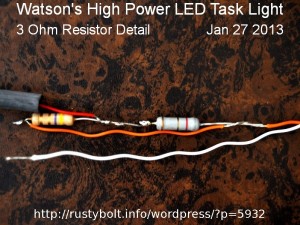
I show a picture of the 4.7 ohm 1W and 8.2 ohm 1 or 2W resistors connected in parallel, with the black heat shrink tubing on the left ready to slide over the whole assembly after I get done.  This has to dissipate about 1.2 watts, so it will get a bit warm, but the heat shrink should protect it from getting any other object warm.  The solder joints outside of this assembly will also have their  own heat shrink tubing.  The 4.7 and 8.2 equal 3 ohms in parallel, but I would have used three 1 ohm, 1/2 watt resistors in series instead.

The Lamp and Mount

The Bivar is mounted to a 2 foot length of 12 AWG solid insulated wire which acts as a gooseneck (see photo).  A stiffer  10 AWG wire would have been better, but I used what I had at that moment.  The other end of this wire is attached to a Pony spring clamp with two wire ties.  I bent a loop in the wire to keep it from slipping in the wire ties.  The clamp just holds onto the edge of a shelf I have on the bench.  I tied  the cat 5 wire to the 12 AWG gooseneck with some small wire ties.  Once the cat5 wire leaves the bench, it connects with the two resistors and then goes to the AC adapter.

The AC adapter doesn’t have a shut off, so I bought a line switch (looks like a cube tap) at the 99 cent or dollar store and plugged the adapter into it, then into the power strip.  This makes it convenient to shut off the light when it isn’t needed.  It also saves a some power – AC adapters are ‘vampires’ that suck a small amount of electric power all the time when they’re plugged in, even if nothing is plugged into them.

The Bivar LED is directed downward where it puts out a lot of light near the work that I’m doing.  The color rendition is very good so I have no problems reading the resistor color codes.  It also is flicker free because it is powered by a DC power supply.

Back to experimenting…

© RustyBolt.Info/wordpress
CyberChimps