


From FB group Building Transistor Radios Larry Daniel 2018-11-26
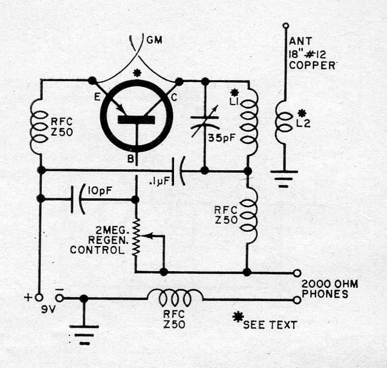
This is the original schematic posted by Larry. GM is a gimmick capacitor made of two short lengths of solid hookup wire, twisted together for a few pF capacitance.
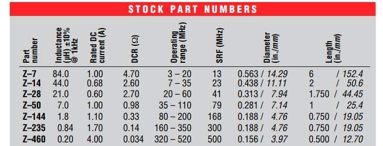
List of RF Chokes for the ham bands
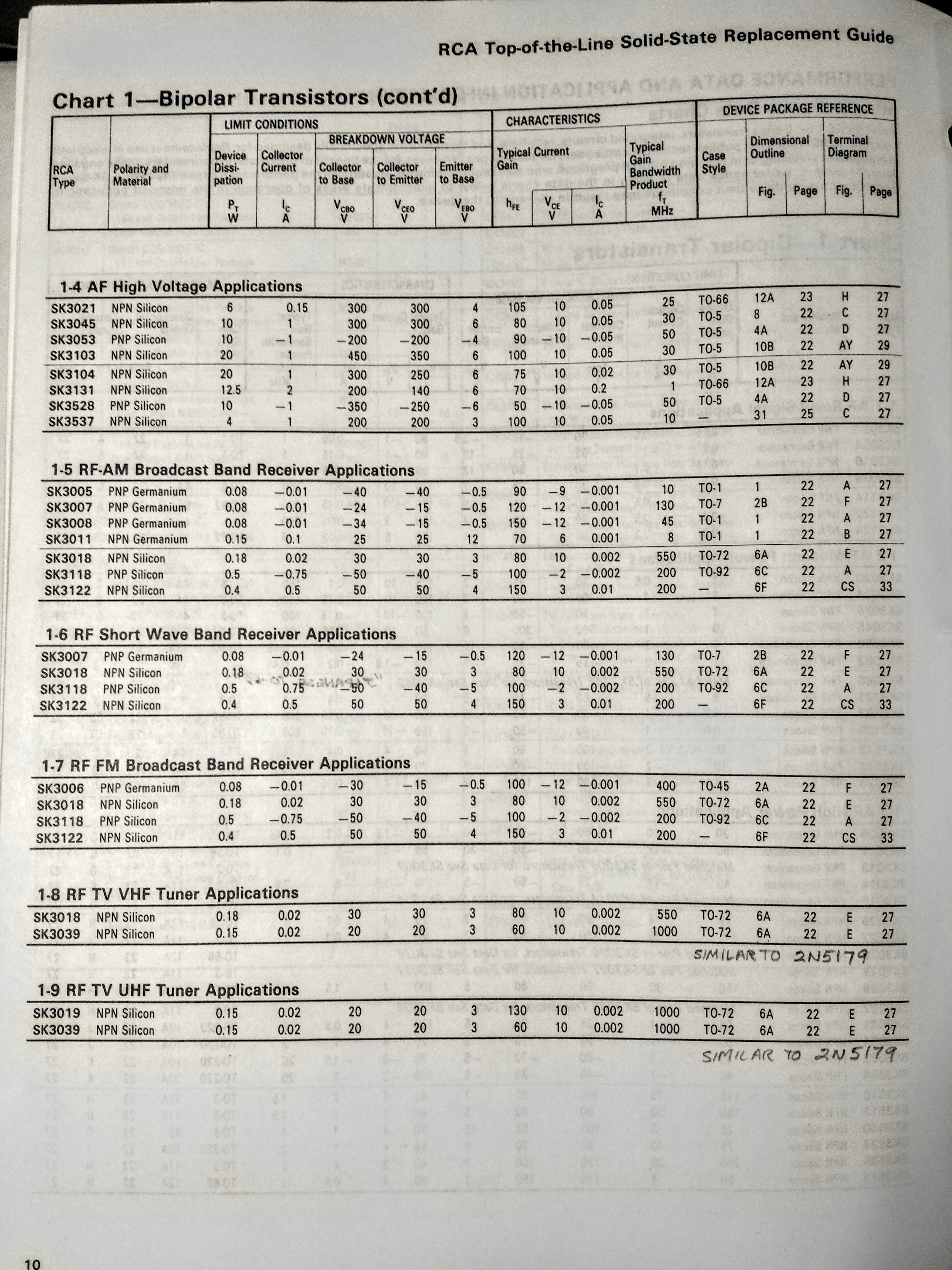
Larry said he used an RCA SK1008, then corrected that to SK3008. But SK3008 only is good to 45 MHz according to the list, and it’s germanium and very difficult to obtain. So battery polarity should be changed and a 2N3904 or BC547 should be used.
Scott Raschke
I used the inductor calculation tool in Electrodroid and got an RF choke
of 36 turns on a diameter of 10mm or 0.394 inch and 20mm or 0.788 inch
length. This gave about 6.8 uH, with a core equivalent to air
(permeability of 1). The AWG wire table shows 26 AWG or 0.4mm diameter
wire should fit on a single layer in that length.
The SRF of the Z50 choke was 76 MHz according to the table. The circuit is operating at FM band frequencies or about 100 MHz. The 7 uH choke has an impedance of about 4400 ohms at 100MHz if its self resonance is ignored, but with an SRF of 76 MHz, the impedance will be lower. It would be best if the choke was lower in uH value and its SRF was higher, 100 MHz or more.
Nothing has been discussed about the tuned inductor. It said ‘See Text’. For a 35 pF tuning capacitor it should be 100 nanohenrys at most. That’s 5 turns 20 AWG wire on a 0.25 inch or 6.4mm form.
Larry Daniel said:
Troops, I suggested this project as a true experimenter challenge. You do not need a lot of parts. In fact you can make most of them and salvage the others. The trick here is by coupling the emitter and collector via minimum capacitance you create an ersatz tunnel diode with a bit of negative resistance. I will let the true experimenter figure out why this might work to detect and demod a strong fm signal. The rfc’s and gimmicks with physical placement of the signal coupling present a true experimental transistor radio. Making this work separates the men from the boys! The cost is very low but the potential to learn is great! Enjoy!
I said:
Larry Daniel
I thought that this circuit was for VHF FM broadcast band. The 2N404 has
a fT ten times lower than the SK3008, only 4 MHz. The same for the
NTE100. It won’t work for frequencies above that.
The only way I could get the 2N404 cheaply was to buy them from a notorious German dealer. Even then they were more than ‘pennies’ apiece.
For VHFs it is best to stay away from germanium and use silicon transistors.
Larry Daniel said:
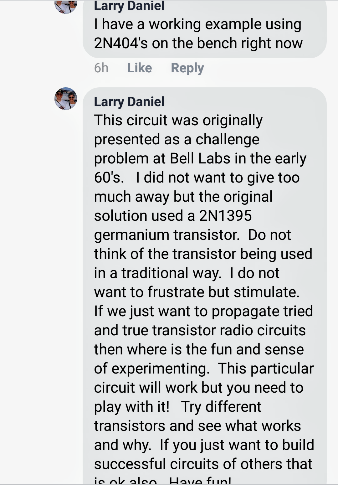
“Understand Watson’s point. I just wanted to put out there a simple transistor radio that had some challenge. BTW, I checked my working version and the RCA germanium transistor is, in fact, an SK3008 not the 2N404 as I stated. I will not recommend any parts or values but with a bit of experimenting you can make this radio work! Have fun!”
The SK3008 has an fT of 45 MCHz as shown in the photo of the chart. I think this transistor would be difficult to obtain.


A 2n384 germanium transistor will work in that circuit. An NTE160 replacement transistor will probably work even better since it can work up to 700 mhz. You are best using a germanium transistor in a circuit designed for germanium transistors. You will likely have to change the biasing too much to move to silicon. You would be better off just looking for a circuit designed for silicon transistors! The biasing needs of the two semiconductor materials are considerably different! By the way, I grew up playing with germanium transistors, so they still are special to me.
The 2N384 is so rare it’s unobtainable. A 2N3904 will work if the power supply polarity is changed.