default

2011-12-09 Germanium Joule Thief

Watson's Ancient Germanium Joule Thief

I have built quite a few germanium JTs, for the simple reason that they will start easily when the battery is below a half volt, and run the battery down to less than 0.2 volts while still putting out a small amount of light. Even after the conventional silicon transistor JT has run the battery down and stopped working, the germanium JT will continue to run off that battery for hours or even days.

In the past several years I bid on and won some lots of transistors, some having germaniums along with various other oddballs.  These and others I collected over the years have enabled me to build germanium Joule Thiefs that can literally suck the life out of a battery like a vampire drains blood from its victim – if you could see the electrons in a battery as red blood, the battery would be a pale and ghostly white after the germanium JT has finished with it.

In the past year I got some more germanium transistors from an eBay seller in Germany, and these were marked 2N404, the number that was as common in the 1960s as 2N3904 is today.  These work very well for sucking the last vestiges of juice from a ‘dead’ battery – I was pleasantly surprised at how well they work.  I used a high permeability ferrite toroid core with enough wire to give about 1 millihenry of inductance, usually about 20 or more turns.  For small cores this usually means the wire has to be thin, so I usually use about 24 inches or 60 cm of 30 AWG, three lengths wound trifilar, all at the same time.  I’m not trying to wind a super low resistance coil, I’m trying to keep the JT running at well below 50 kHz.  Two of the windings are connected in parallel for the primary.

Since most germanium transistors are PNP, including the 2N404, the positive battery line goes to common or ground, and the negative to the two windings, in other words the opposite of the normal connection for a silicon JT.  Also the LED’s cathode or flat spot must be connected to the collector.  I use the optional capacitor across the battery, and it is typically a 10 microfarad polarized electrolytic with the positive end to the positive of the battery, which is the JT’s common or ground.

I use a resistor that is lower than 1000 ohms or 1k ohms, although a 1k works okay.  I usually use a 470 ohm resistor to drain the battery a bit faster.  But this will cause the germanium JT to draw too much current if it is connected to a fresh battery, so i don’t connect it to fresh cells.

The LED is not critical; any color LED will do.  Typically I use the blue LED.  I bought a few dozen blue LEDs from a seller on eBay, and when I received them found that they (and other colors) had air bubbles in the lens.  I informed the seller, who sent me replacements, so I have even more blue LEDs.  I’m still trying to use up the various colors with the air bubbles.   I even have one germanium JT with an ultraviolet LED, which is supposed to be able to detect counterfeit bills.  I haven’t found any yet (thankfully..).

The picture shows a germanium Joule Thief made with a transistor from an old computer board, one of the many that were made surplus back in the early 1960s when the SSI chips (7400 series small scale integrated circuits) became available and computer (mainframe) makers replaced all of those old transistors.  The date code is 5926, or the 26th week of 1959, over 50 years ago.  But the transistor is still going strong, mainly because at that time they had learned enough about packaging transistors to hermetically seal the chip inside of a metal package.  The transistor is similar to the ones General Electric sold, but it has a house number, maybe from IBM.  We have to remember that germanium transistors were only capable of running at 1 to a few megahertz, so when silicon parts came along, the clock speeds could be dramatically increased.  The poor li’l germanium transistors were quickly abandoned for silicon.

The clothespin button cell holder allowed me to run those alkaline button cells down to nearly zero volts. One thing I’ve noticed is that the alkaline AA and AAA cells tend to leak, even if they are old but unused (I took some old ones out of a package recently and the ends were all furry from the leaked juice).  But I can’t remember ever seeing an alkaline button cell that has leaked.

Back to experimenting…

default

2011-12-07 Watsonseblog May Live Again

I received emails with most of my blogs that were archived by Yahoo.  There are 35 meg worth, I’m guessing about 700 or so.  I found that I will have to add them manually, which is a major chore.  I have to sort through them and decide which ones were the most popular.  Looks like a lotta work ahead.

default

2011-12-04 Joule Thief Conventional & Supercharged

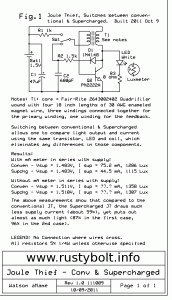
Clarification: People have asked if the three windings explained in the schematic are in series or parallel. The three are in parallel, in other words, solder three of them together on each end. But make sure you use an ohmmeter to find and separate the other (4th or feedback) winding from the three.

In Jan, 2009 I designed a circuit that removed the Schottky and capacitor from between the collector and LED and instead used it (or a regular 1N4148 diode) only to rectify and filter the coil output only for the transistor base bias. My reasoning was that the losses in the diode would be reduced – much less current through the diode – and more power would then go to the LED. I found out that when I used a 560 pF to 1000 pF capacitor for the filter cap, the circuit was much more efficient than when the capacitor was larger. I called this a Supercharged Joule Thief.

In October 2011 I added a switch to a JT to allow switching between conventional Joule Thief and Supercharged. I used a luxmeter to measure the actual light output of the LED.  There was no measuring of the current through the LED, so there was no question of if or how the ammeter or voltmeter might influence the reading because of the pulses from the JT.

As I show in the schematic, the performance difference is significant between the two types.  My Supercharged Joule Thief has much less power consumption for almost the same amount of light.  In other words, it is much more efficient, greener and wastes less energy than a conventional JT.

The switch allows me to switch between the conventional Joule Thief and the Supercharged Joule Thief.  Since the LED and most of the rest of the circuit is the same for both measurements, there is no difference in the measurements caused by a difference in the circuit or the LED’s light output.  This “apples to apples” comparison is important: it narrows down the efficiency difference to the changed components and only the changed components.

I used a 1 ohm resistor in series with the LED to measure the LED current. I assumed the voltage across the LED was 3.3 volts.  When I calculated the SJT efficiency, I sometimes came up with a figure above 90 percent, but typically it was in the high 80s.  This compared to 40 to 60 percent for a conventional JT.

I have corresponded with others and some have insisted that using this resistor in series with the LED to measure the LED current is not accurate.  The problem seems to be with the way that the digital voltmeter measures the rectified pulses.  I decided that the way to end this controversy is to measure the LED light output.  I bought an inexpensive luxmeter for about $40 (USD).  I glued the LED to a hole in the end of a small cardboard box which holds the LED a fixed distance from the luxmeter sensor, and blocks all ambient light.  The LED is a white 10mm that can handle a watt for a short period – long enough to make a lux measurement.

My Supercharged JT was published on my late, great watsonseblog since 2009.  I sometimes wonder if anyone considered adopting it to replace the conventional JT.  It is well worth the very few changes and parts needed and almost no difference in cost.

If my SJT is compared to a conventional JT with a Schottky diode and filter capacitor on the output, I can’t see how the Schottky/filter capacitor JT could come close to the efficiency of the SJT, because of the losses in the voltage drop across the Schottky diode.

Previously in my blog I measured the efficiency of a conventional JT and my SJT.  I used the supply voltage times the supply current to get input power.  I measured the voltage across  a 1 ohm current sense resistor in series with the LED.  I multiplied this current times 3.3V for the LED forward voltage to get the output power.  Then I divided the output power by the input power to get the efficiency.

I have to go by my memory (my blog is now gone).  I was getting around 50% to 55% efficiency for a conventional JT, and my SJT was getting 80% to 90% efficiency.  The difference was very significant.  But some, including myself, doubted the measurements, so that’s why I bought the luxmeter – I could make a comparison of the actual light output.  And as I showed above, this agrees with the earlier efficiency measurements I made.

Back to experimenting…

default

2011-12-03 Low Voltage Joule Thief – TN0702 MOSFET

In Jan 2009 I collaborated with Quantsuff and we tried different designs for a low voltage Joule Thief.  The conventional silicon BJT Joule Thief (bipolar junction transistor) has a base to emitter forward voltage of about 0.55 to 0.6 volts, so if the supply is below this voltage it will not start.  But once it gets started, it will run to below 0.5V, maybe down to 0.35V.  We can change the transistor to a germanium, which is an ancient 1950s transistor technology no longer made.  The germanium’s forward voltage is about 0.2 to 0.25 volts, so the germanium BJT Joule Thief will start up at half the voltage of a silicon BJT.  But as I said, these are old transistors no longer made and difficult to obtain, and the reasonably priced ones can’t handle a large amount of current and power.

One idea QS had was to use a switch to charge a capacitor when the JT was off.  Then when the switch was turned on, the capacitor’s voltage was added to the supply voltage, and the JT would start up.  The supply voltage could be as low as 0.3 volts, and the added voltage would be 0.6V, enough to start the JT.  Cool.  But someone had to switch the switch every time it had to be powered up.  About that time solar LED garden lights became cheap and experimenters like Bill Sherman were buying them, opening them up and experimenting with the parts.  If you built solar garden lights with a half volt solar cell and the switch and capacitor to start them, you would have to walk around to every garden light to switch the switch to turn it on.  Obviously this was not a very practical solution.

The Law of Diminishing Returns  Another problem at low voltages was getting enough power to light the LED reasonably bright.  Let’s say we have a JT that puts out enough current to the LED, say 10 milliamps, with the 1.5V cell supplying a current of 50 milliamps. The 1.5V times the 50 milliamps is 75 milliwatts drawn from the cell.  The JT is boosting the 1.5V cell up to about 3 volts across the LED, or about doubling the voltage.

We want to run the JT at half that voltage, 0.75 volts, but we still want the LED current to be 10 milliamps.  We lower the supply voltage down to 0.75 volts, but the current from the cell and the current to the LED drop dramatically.  We have to do something to bring the LED current up to 10 mA, so we replace the 1k resistor that is used in the conventional JT with a lower value.  This helps some.  We look at what the JT needs to do the same job that it was doing at 1.5V.  When the supply voltage is cut in half, the supply current needs to be doubled in order for the JT to draw the same amount of power from the supply.  Therefore the supply has to see a load that is one quarter the resistance. Yes, the voltage will be half, and the current will be double, so the load has to be 1/4 the resistance in order to draw the same power.  Also, the JT has to boost the voltage from 0.75 volts up to 3 volts, or four times higher.

We look at the components: the supply, the transistor, the coil, the resistor, the wiring (the LED has to stay the same; it can’t have a lower forward voltage).  The transistor has to conduct twice as much current at half the supply voltage, so it has four or more times the demand put on it.  The coil has to handle twice the current at half the voltage, so the DC resistance of the primary winding must be reduced to 1/4 to keep the losses down to the same level.  This means the wire has to be much heavier to handle the higher current and lower voltage.  And the coil has to boost the voltage twice as high as it did previously so it has a greater demand put on it.  The supply has to supply twice the current, or 100 milliamps to the JT, so the demand has doubled on the battery.  Also the resistor has to be reduced to 1/4 (or more) because the transistor has to handle twice the collector current, which means at least twice the base bias current, and at half the supply voltage. And remember, we have only reduced the supply voltage to 0.75V, which is half of 1.5V.

When we again reduce the supply voltage by half to 0.375 volts, the supply current again doubles to 200 milliamps.  The demands again multiply exponentially, so that things that were insignificant before at 1.5V are now becoming really significant and can cause problems if not taken care of.  An example is the size of the copper traces (‘wires’ or conductors) on the circuit board have to be much heavier to handle the greatly increased current.  The bypass capacitors have to be much larger to handle the much higher currents.  The length of the circuit board traces may become a problem because they add inductance, and may interact with the coil and capacitors.  The resistor has to again be reduced by 1/4, so it is now down to 62 ohms (1/16th of its original 1000 ohm value).  My whole point of this explanation is we are reaching a point where the Law of Diminishing Returns begins to eat away at our results, and it becomes much, much more difficult to do what seemed relatively easy at 1.5 volts.

MOSFETs  I experimented with the MOSFET augmented Joule Thief using a 2N7000 and a 2N3904 BJT.  It worked fine, but it would not start reliably below 0.6 volts.  I brainstormed and came up with the idea that since the gate of a MOSFET does not need any current, only voltage, I could put a button cell in there and it would reduce the gate voltage to less than 1 volt.  This worked well for the 2N7000 Joule Thief.  But we really wanted to get the JT to start and run at voltages below 0.6V and also put out a reasonable amount of current, which the silicon and germanium JTs could not do at very low voltages.

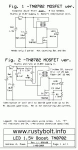
I ordered some TN0702 low gate threshold voltage MOSFETs.  These are low power devices; they are not power MOSFETs.  But one can put out enough current at low voltage to drive the LED of a Joule Thief to reasonably bright current.  The first circuit I built with one was a MOSFET JT that did not need a resistor, and was the simplest Joule Thief possible, only three parts: a coil, a TN0702, and a LED (not counting the battery and on.off switch) (see Fig.1 of the schematic).  I blogged this and it became one of the more popular of my blogs because the search engines gave it a lot of hits when people searched for low voltage Joule Thief.

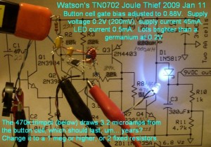
Considering the demands I pointed out above, the TN0702 worked as well as could be expected in the JT circuit I made (see the pictures).  The extreme demands put on it at a supply voltage of only 0.2 volts made it impossible to supply as much LED current as a JT at 1.5V, but it did as much as it could, and I measured 0.5 milliamps LED current.  That doesn’t seem like much but it was far greater than I had ever been able to do with a JT at a supply voltage of only 0.2 volts.  The supply current was only 45 milliamps, but again that was much more than any germanium transistor was able to do (silicon transistors were useless – not able to go below a half volt).

The article found here (.PDF) explains the theory and construction of a DC-DC converter with an input of 350 millivolts (0.35V) and an output of 5 V for running a microprocessor or other device, meant to be supplied by a thermoelectric generator (TEG).  TEGs are often made with Peltier junction devices, which are also used in small coolers that plug into the 12V car power.  In this case the TEG was a thermopile.

Back to experimenting…

default

2011-12-02 Watson’s Blue Blinky Joule Thief Flasher

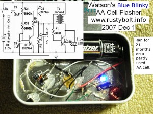
I built this Blue Blinky and installed the partly used AA cell on Dec 1, 2007.  For most of the next 21 months, on or about the first of the month I published a short blog on how it was doing.  As the cell ran down it got dimmer and dimmer, but continued to flash, with the speed increasing toward the end.  If I remember correctly, the cell’s voltage dropped down to under 0.8 volts, and it still kept on blinking.  I think it deserves a prominent place because of the apparent low current draw and longevity of the battery.  I uploaded a 20 sec video of them flashing to Youtube, so check it out.  The middle two turn off when I shine the light on them, the top and bottom don’t turn off because they don’t have the LED sensor.  And it’s cheaper and easier to get a red LED than a CdS photocell.

I have come across several of the circuits on David Johnson’s website that have very long battery life, but those usually have a CMOS chip, which inherently is very low current.  My Blue Blinky uses three regular transistors and doesn’t require any chips, and does a good job of being a current miser with a long battery life.

Daylight shutoff  I updated the schematic (not shown on this one) to include a CdS photocell across the emitter to base of Q3.  When the Blue Blinky is in the dark, it will run, and when the ambient light is like that in a normally lit room it will shut off.  This should double the lifetime of the battery depending on the light/dark ratio. Having the room lights on after dark may keep it off, so the battery life may be further extended.  But I really don’t have another 2 to 4 years to test it and find out. 😛

One reason I say “test it” is because the photocell will shut off the flasher part. A JT, for instance, may run, if left undisturbed, until the cell voltage drops below 0.5 volts (some have claimed lower than 0.4V). As long as the JT is running, there is enough voltage to keep it running.  But if you disconnect the cell, when it is reconnected the JT may not start until the cell voltage rises to around 0.6V.

Because the Blue Blinky will flash down to a battery voltage of below 0.8 volts if left undisturbed (without a photocell that turns it off every day), I could not say for certain if it would work down to that low battery voltage with the photocell turning it on and off.  I guess one could check its performance by using a ‘dead’ AA cell that has a voltage of less than 1 volt, and running it for a few months on what little ‘juice’ is left in that cell.  At least one would not have to wait for years.

Operation  I used a standard two transistor flasher circuit found at a number of places on the net, including Bill Bowden’s website.  However it does not have to supply the 70 or more mA current the Joule Thief requires, it only has to supply the base bias current to the base of the JT transistor, which is only a milliamp or less.  The flash rate is determined by the C4 1uF capacitor and the two resistors R3A and B.  I found that if R3 is too low, the flasher can become unstable and refuse to flash or turn fully on.  I think it is better to keep R3 at more than 1 megohm, and change C4 if you want to adjust the flash rate.

The Joule Thief part of the circuit is pretty much just a standard JT.  It uses a coil made from a ICH-YJ41003TC core, with ten turns of 24 AWG solid telephone wire, and 10 turns of 30 AWG enameled magnet wire.  The coil inductance is in the mid to high 200s of microhenrys.  The feedback winding is not connected to the battery, instead it is connected to the flasher’s output.  The flasher’s short pulse turns on the JT for a short period of time and the blue LED lights up brightly.  The relatively long stretch of dark time between blinks is what extends the battery life.  The flasher, as I said, turns the base bias to the JT on for a very short period of time; it is off most of the time.  This is how the Blue Blinky makes the battery last so long.

The C5 bypasses the pulses of the feedback winding to minus, so that the base of Q1 gets its full voltage as if the winding was directly connected to positive. (Now that I reread the preceding sentence, it sounds too abstruse [difficult to comprehend])  The R5 resistor is to discharge C5 so the JT stops abruptly.  I have not tried changing it or removing it, but the JT may work as well with a higher value or with it removed.  But then see the June 25, 2012 update below.

Update Dec 9, 2011 – I have spent a lot of time the last few evenings designing the ‘Blue Blinky’ PC board with ExpressPCB.  I started out with a rectangular board not far from being square.  I could get 6 of them on a “miniboard” (size 2.5″ by 3.8″). But then I realized I could save a battery holder by making the PC board longer and about as wide as a AA cell.  The contacts on the ends of the board will be made out of a loop of steel wire cut from the end of a heavy paper clip. I got this idea here.  I bought some of his Night Joule Thief boards and built a few so I know they work okay (BTW this guy has some fantastic LED art – check out his website). I decided to change from the nearly square rectangular board to a much longer and thinner board to allow it to become the battery holder.  It’s tedious work but I pretty much have it down to where I want it, and I can get five of them on a miniboard, so a standard order of three miniboards or fifteen of the PCBs will come to something around 65 dollars US.  That’s about $4.33 a PC board, but I’ll have to cut them up when they arrive.  The glass epoxy board is hard on the mini hacksaw blades I use so I’ll wear out a few of those and it will cost somewhat more as a consequence, not to mention a little sweat equity.  But hey, that’s what it’s all about — it’s a hobby(?)…

Update Dec 10 – In my Blinky I first used the CdS photocells just like I discussed above. But CdS photocells are uncommon, whereas red LEDs are as common as dog doo-doo.  So I changed over to a red LED used as a light sensor (maybe I should call it a LSD or light sensing diode).  The LED is just like a photovoltaic solar cell but the surface area is very tiny, so it can only generate microamps.  But that’s good enough to drive the base of a transistor which then amplifies the current up to whatever is needed.  I just put the red LED between the base and emitter of a 2N3904 and it will turn the transistor on when it’s lit.  I connected the 2N3904 transistor’s emitter to negative and collector to the base of Q2.  The LED turns on the 2N3904 so it shorts out the current coming through the two 680k resistors and the flasher circuit cannot flash any more.  The two 680k (or one 1.3M) resistors will conduct a microamp or so during shutoff, which is so low that it would take many, many years to drain the battery.

LSD Sensitivity  The LSD (light sensing diode) shuts off the Blue Blinky when it’s daytime outside, even in the shade.  But inside the ambient light is lower, and my only problem is that the clear lens red LEDs I used are very directional, and only turn it off when the LSD is pointed directly at the ceiling light.  So I have to figure out how to get the LED to turn on when light is shining from the sides.  Maybe I can diffuse the light by making the LED rough on the top with some sandpaper. Well, I tried dulling the top of the light sensing LED with some sandpaper. It still is directional.  The dullness reduces the light a bit so it’s probably less sensitive.  But it still turns off when I point the top of the LED towards the ceiling light. I changed to an orange LED, hoping it would be a bit more sensitive, but it is still directional.  I sawed off the round top of the led so the lens was flat, then polished it with some very fine sandpaper to smooth the roughness out.  It lost too much sensitivity, and wouldn’t turn off when I pointed it at the ceiling light.  I changed it back to a regular red LED.

I had been using the PN2222A for the LSD current amplifier.  This transistor has a medium to high gain of 100 to 300 at 10 ma current.  But the LSD puts out a few microamps, and the PN2222A amplifies that to a small fraction of a milliamp at a fraction of a volt.  The datasheet for the PN2222A says that the gain could be as low as 35 at 1/10 milliamp.  In other words, the PN2222A’s current gain gets much lower at low currents.  What I need is a transistor that has high gain at low currents.  I chose the BC550C, which is made for low current, low noise amplifiers (it is the same as the BC547C).  It has a current gain of 420 to 800 at 2 mA, which is a lot more than the PN2222A.  I removed the PN2222A and put in the BC550C, and the difference is like night and day, no pun intended.  The LSD now turns off the Blue Blinky  with just the ambient room light; it does not have to be pointed at the ceiling light.

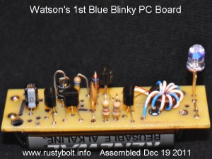
Update Dec 19 – I received the Blue Blinky PC boards yesterday morning and sawed one off, and assembled it (see the picture nearby).  It worked like a champion as soon as I connected the AA cell, but I had to bend the heavy paper clip battery contacts a bit to get the battery to stay in its place.  The flash rate is a bit faster than 1 per second, actually about 1.1 per second.  I’ve since assembled three more, and all work just fine.  One had two red LEDs in series in place of the blue LED, but a Red Blinky just doesn’t have that poetic sound to it.  By the way, the picture to the right does not show the red “LSD” directly behind the leftmost transistor – it works great without it.

Update Jan 15 2012  Another pic of a slightly modified PC board, which I received in another order.  I positioned the battery clips so they were closer to the ends of the AA cell.  A few other mods,  but it looks a lot like the original boards.  I’m happy with the battery holders, I have used paper clips and heavy bare copper wire, I think it’s 20 AWG or 18 AWG.  I changed the .01 uF capacitor to .001 or 1 nF, which seems to work just as well.  I used two yellow LEDs on this board. I haven’t installed the red LED used for sensing the light.  I changed the transistor farthest to the left from PN2222 to BC550C, which is more sensitive to light.  The resistor laying on the board behind the electrolytic cap is a 1.5 megohm which replaces the two 680k resistors; it determines the flash rate.  The reason I originally used two 680k resistors in series was that the total added up to 1360k, which was closer to the 1 second flash rate I wanted.  But the 1 μF is an electrolytic, which has a typical tolerance of + or – 20%.  That’s quite wide, so I figured that I could put a 1 Meg resistor in one of the two positions, and then use a pot to adjust the flash rate to about 1 second.  When I’ve found the optimum point, I remove and measure the pot, and then put in a resistor close to that value, such as 390k.  But I’ve been putting in two 680k or a 1.3 Meg, and that’s close enough.  Changes in the temperature will cause variations in the flash rate, so it’s not really possible to get it exactly 1 second.

Back to experimenting…

default

2011-12-01 Joule Thief Coil Explained

Ωne of the readers of my late, great watsonseblog sent me an email and asked some questions about the Joule Thief coil.

But before I get up to speed I think it would be a good idea to read the warning at the end of this blog.

my Q was: what is the relationship of the coil and/or wire to the performance of the circuit (assuming other components are constant)?

from what i remember in your answers, the fatter the wire, the more current flows to the led. also, more turns makes higher inductance but lower frequency. what then is the factor for voltage?

my understanding is that we only need enough turns to make the circuit kick into oscillation, and as long as the circuit puts out at least 3.5v, the led will light up.

additional Q’s:

– which is the primary winding? secondary? is there a naming convention for this?

– which coil should be fatter/more turns?


I think I should start with the last two Q’s to clear up any confusion about terminology. It will also help the neophyte experimenter understand the Joule Thief, which I will abbreviate to JT.

Coil  The typical JT coil consists of two windings; each winding consists of from less than 10 to more than 25 turns, wound on a ferrite toroid which looks like a tiny donut (but remember that other types of coils can be used, too).   The primary winding carries almost all of the current and is the heavier of the two windings; the feedback winding can be very fine wire because it carries very little current (but it doesn’t harm anything if it’s the same size wire as the primary).  Both windings are wound onto the core at the same time and have the same number of turns; this is called bifilar wound.  Winding both at the same time is easier, but the windings can be wound separately.

Windings  The primary winding’s leads are connected to the transistor’s collector and to the positive end of the battery (when the transistor is NPN).  One end of the feedback winding is also connected to the battery positive; the other end is connected to one end of a 1000 ohm (1k ohm) resistor; the other end of the resistor is connected to the base of the transistor. The two ends connected to the positive are not at the same end of the coil; the feedback winding’s leads should ‘cross over.’  The second winding is called the feedback winding because that is all it does.  There is no secondary winding because the voltage conversion is all done in the primary winding. The feedback just keeps the transistor turning on and off.  A winding would be secondary if it was a transformer, but it is not a transformer.

That answers the 2 additional questions at the end.  Now for the rest, starting with the coil’s relationship question.

The coil is important because all of the current flows through it, and most of the current flows through the primary winding.  The battery current can reach a half amp or more, so the DC resistance of the primary winding must be very low, to let the current freely flow. There is going to be some voltage drop across the transistor and the battery voltage is going to be less than 1.5V, so at most the primary winding will have a volt or less to push the current through it.  If the DC resistance of the primary wire is 1 ohm and 1 volt is across it, and 1 amp of current is flowing, then the wire will dissipate 1 watt; that is wasted energy that does not go to the LED, but gets wasted as heat in the wire.  So the DC resistance of the primary wire must be much less than 1 ohm to prevent waste and inefficiency.  And this last sentence above answers the second question, “what is the factor for voltage?”  Again, the DC resistance of the primary must be low so that the voltage drop across the primary winding is kept low.

Wire Size  Let’s say I’m using 30 AWG copper wire (countries that use metric wire have a wire table in ohms per thousand meters).  The copper wire table says that 30 AWG has 104 ohms per thousand feet, which is about the same as 1/10 of an ohm per foot (actually 0.104 ohms per foot but we’ll round it off).  Suppose the primary winding has a length of 10 feet.  Then the total DC resistance will be 1 ohm, and that is too high. Instead we use 24 AWG, which has a DC resistance of 25.7 ohms per 1000 feet, which is about the same as .0257 ohms per foot, and is one quarter the resistance of 30 AWG.  A ten foot length will have a DC resistance of about 1/4 ohm, which is getting down to (or we could say approaching) the point where the power loss will be low and the efficiency will be reasonably good.

“…we only need enough turns…”  is the last question and it involves some math.  The coil is required because it is where the energy is stored in the magnetic field.  Think of the battery as a lake or stream, and the LED is like a 5 gallon or 20 liter container in the bed of your truck, parked next to the lake or stream.  And you have to fill this container by scooping up water in your ‘filling container’ and emptying it into this 5 gallon container in the truck.  You start out dipping a drinking glass that holds a pint or half liter in the lake and emptying it onto the container. After a dozen or so of that, you say to yourself, this is going to take a long time!  I need a bigger filling container.  So you go get a wide mouth bottle that holds 2 liters or half gallon, and start dipping it into the lake and filling the container.  Things are going much better and the job gets done reasonably fast.

The math

The amount of energy stored in the coil is equal to the one half of the inductance times the current squared, or L*I^2/2.  So we can double the inductance and increase the energy stored to double.  Or we can double the current and increase the energy stored to four times, because it’s the current squared, or the current times itself – current times current.  The voltage remains the same across the JT coil.  We can increase the energy stored by using fewer turns, and we lower the inductance by half, but the DC resistance is half, the current doubles, and the energy is doubled and doubled, or four times (the current squared or current times itself).  We sacrifice inductance to get more current and even more energy stored.

We have the LED and a JT coil.  The coil has thinner wire and a large inductance, but a lot of wire is needed to make the inductance so the DC resistance is high.  We have less than 1 volt to push the current through the high DC resistance, the amount of energy stored is small because the current is low, and every time the transistor switches on and off, it is like using the small glass to fill the big container: the amount of energy transferred or the amount of water moved is low, and the container takes a long time to fill, and the LED is dim because of the low current.

We remove the thin wire and put heavier wire on the coil, and now we have half the DC resistance. Since the voltage stays the same, half the resistance allows twice the current.  The inductance is half so the energy stored is half.  BUT the current has doubled and the energy stored has doubled and doubled (current squared).  We have sacrificed half the inductance to get twice more current and four times the energy stored!  And the LED is much brighter.  It’s like we are filling the container with the bigger 2 liter bottle.

Gotcha time.  But now the transistor has to switch twice the current.  And the transistor is on for part of the time, let’s say half the time.  That means when it is on, it has to handle twice as much current when it’s on.  The JT demands that the transistor handle a high current for a short time, and the transistor must be very low DC resistance and capable of handling high current.  The transistors that are made for amplifiers that run at a few milliamps have too high resistance and can’t handle the high current (like the 2N3904 and BC547).  We have to use a transistor that can handle a half amp or more.

The typical Joule Thief must put out about 66 milliwatts to the LED, which is 20 milliamps times 3.3 volts.  If the JT is 50 percent efficient, then the battery has to supply twice that or 132 milliwatts.  That’s 88 milliamps at 1.5 volts.  The typical JT runs in the 75 to 90 milliiamps at 1.5VDC. But that’s average battery current.  The peak current is at least twice that much when the transistor is turned on.

Another question that I’ve been asked is how many LEDs can I connect in series across the transistor?  Assuming that the LED is white or blue, then its forward voltage is about 3.3 volts at full brightness.  If we connect two of these LEDs in series the total will be about 6.6 volts.  That’s okay for the voltage across the transistor from emitter to collector, which is typically 20 volts maximum or more.  But we have to remember that the feedback winding has the same number of turns as the primary winding, so it will have the same voltage, but in the opposite polarity.  For two LEDs, the negative voltage acrpss the feedback winding will then be -6.6V.  We subtract the 1.5V supply from -6.6V and it is 5.1V.  The absolute maximum emitter to base voltage for most silicon transistors is typically only 5 volts, with some (very few) transistors rated at 6 volts.  So this -5.1V can cause damage to the transistor.  If you add LEDs in series, then the number of turns in the feedback winding should be reduced so that the negative voltage on the base will be lower.  Or else put the LEDs in parallel so the voltage will stay at about 3.3 volts.

Another way to do this is to add another winding (which will really be a secondary winding) with many more turns for much higher voltage to accommodate many LEDs in series.  But this is deviating away from a simple JT so it will have to wait for another blog in the future.

I hope I’ve answered the questions in an understandable manner.  Back to experimenting…

Warning

I, and many others often use Wikipedia to get up to speed when reading about something on the ‘Net.  But the Wikipedia article on Joule Thief couldn’t be a worse place to start reading about a Joule Thief.
The Wikipedia article on Joule Thief is erroneous, incomplete and in a constant state of flux because of many well-meaning but misguided individuals who try unsuccessfully to explain what it is and how it works.  One example is the recurring use of the term transformer.  This in an incorrect term for the coil.  The JT coil has the primary winding which is the only winding needed for operation.  The feedback winding is there just to invert the signal to keep the transistor switching, and can be eliminated by replacing it with another transistor.  There are a number of so-called “Joule Thiefs” found on the net that use a two transistor circuit and a coil with a single winding.  The circuit originally named Joule Thief has only a single transistor.  As for the Wikipedia article, my best advice is to avoid it. If you try to understand it now, then come back later when you think you have learned enough about a JT, you may be disappointed to find that the article is even worse than it was the first time you read it.


default

2011-11-29 Joule Thief pictorial diagram

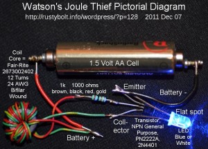
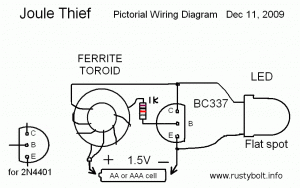
This is a pictorial diagram of a Joule Thief (JT). It is meant to give a simple visual guide to those who wish to assemble their own JT.  I’m also adding sort of a Joule Thief FAQ to explain in simple terms what a JT is.

JT – WHAT IS IT? A conventional Joule Thief is a simple, easy to build a circuit that consists of the following components: (refer to the accompanying drawing)

1. A battery (it’s at the bottom), typically a single 1.5V AA or AAA cell, to supply power to the JT circuit. The battery voltage must be less than the voltage that lights the LED (which is 2V for red, 2 2 to 2.5 volts for orange and yellow, around 2.7 volts for green, and 3.2 volts or more for blue and white LEDs).

2. A LED (Light Emitting Diode) (it’s on the right), typically a white or blue LED, but other visible colors will also work. The forward voltage of a white or blue LED is about 3.2V, but the LED will begin to light up below 3 volts.

3. A transistor (it’s in the middle) to switch the current to the coil (inductor) on and off rapidly. This transistor is typically NPN, and some common types are the 2N4401, PN2222A, BC337-25, 2N3904, BC547. The last two types are not capable of lighting the LED to full brightness. “But they work,” says the neophyte experimenter. The JT’s maximum current exceeds their maximum rating, and the result is excessive losses and poor efficiency.  A good choice for a transistor is one that has low Vce(sat) at low voltage, high gain, and can handle several hundred milliamps of current. See the transistor’s datasheet for more information.

4. The coil or inductor (it’s on the left).  This has two windings, the primary or main winding, and the feedback winding. The primary winding is the only winding needed to light the LED; the feedback winding is there only to keep the circuit running and to switch the transistor on and off. Therefore, the coil does not transform the voltage, which is actually increased by the counter EMF of the primary winding.  The coil/inductor is typically wound on a toroid core, which looks like a tiny doughnut. Both windings are typically wound at the same time, which is called bifilar wound.  In the pictorial, it shows two separate windings, wound so that the coil looks like it is tapped in the center, where the battery’s positive connects to it (for clarity, only six turns are shown; a typical coil will have 12 or more turns).  When a core is wound with both windings at the same time, and the end of the first winding is connected to the start of the second winding, it is the same as the winding shown with the tap in the center.  Other forms of coils will also work, including an air core coil.

5. The resistor (colored rectangle to left of transistor), typically 1000 ohms or 1k (brown, black, red, gold stripes). This limits the base bias current which flows from the battery positive through the feedback winding to the transistor’s base.  Most common is the 1/4 watt resistor, but 1/2 watt will work, it just takes up more room.

Optionally, the battery is bypassed with an electrolytic capacitor typically 10 or more microfarads (not shown). It is considered best practice to include this even though the circuit will work without it.  Some JT circuits add a small capacitor, typically a few hundred to 1000 picofarads across the resistor.  This seems to help increase the brightness and efficiency of the JT.

These five components are what were in the original circuit named the Joule Thief.  Some experimenters incorrectly give the “Joule Thief” name to other circuits that perform a similar function, but they are not a true JT.

Back to experimenting…

default

2011-11-28 Conspiracy Theory

This is about a guy who recently posted a video based on “Free Energy” or overunity on Youtube. This guy seems very innovative, he builds a lot of stuff.  He calls himself my video is on utube (with no spaces). I asked him for permission to put some of the messages here but he didn’t reply yes or no, so I’ going to use some excerpts.  He built a Bedini SSG and showed it running. A Bedini SSG is a wheel with magnets and a simple circuit that keeps it running. This is then connected to a second “charging” battery and it charges this battery.  Bedini (or someone, maybe not Bedini himself) claims that it uses less power than what it puts out to the battery it is charging.  Sounds like an “overunity” claim to me. It puts out pulses to the battery being charged, and this is supposed to remove sulfation, which is why I got interested in it.   I left a comment about one video where he said something to the effect that he would mount a generator and pulley next to the wheel and tap off enough power to keep it running without the running battery. Basically he will have a device that generates more power than it uses, or essentially a perpetual motion machine.  My comment was that he shouldn’t set his hopes too high, it was not likely to work.

So then he sent me a message claiming, well, you can read it. His mind is made up about the world being a big conspiracy.  And he claims this is a “fact.”

“The fact of the matter is……yes, they already invented free energy devices, and cars that run on water. The reason why you don’t see them in production is because the big corporations of the world either bought the patents up and threw them away, or they would have you killed. That is the fact, and that is how this wonderful world works. All about money.”

He goes on with a diatribe on cancer cures are being covered up because the big companies would lose all the billions they are making on drugs, radiation therapy, etc.

I replied

I don’t believe in the conspiracy theories.  I see through them and see that the experimenter is using this as a coverup for his failure at building a perpetual motion machine.  But I do believe in Free Energy. This summer I went down to the Port of L.A. and visited the USS Abraham Lincoln, which is a nuclear powered aircraft carrier.  They can steam along at (classified) knots, without refueling for a year or two. They get enough power and heat from the reactor to make all their fresh water from the ocean.  Then there is that Mars rover Curiosity that launched Saturday, with the rover the size of a Mini Cooper.  The whole thing is being powered for several years by a nuclear generator.  So we can get free energy, but no one wants to invest in it because it is so dangerous (Fukushima Daiichi).  Years ago these two scientists at U. of Utah started the Cold Fusion fiasco, and had the media going for awhile.  But it didn’t amount to anything. I’ve watched supposedly free energy videos on Youtube and seen how they are just like magicians: they use trickery, video editing or illusion to try to make people believe.  [snip]   I’ve tried, as so many others have, to reproduce some of the “overunity” devices that have been on YT, among many other places.  I might get part way, but never reach that point where it can run itself.  One has to be honest with himself and keep his feet on the ground, even if he has his head in the clouds.

He then replied with a message accusing me of being narrow minded (!!!). Then he brought up politics and made another accusation.

As for free energy, cars running on water….etc….yes, some are fakes,I agree, but some are real whether you believe it or not. You seem very narrow minded. You have to be more open minded about things and willing to look at facts, and do extensive research before you come to your conclusions. These are mostly conspiracy FACTS, not theories. Just like you don’t believe everything you hear on TV(I hope you dont…LOL), you don’t believe everything you hear on the net. I’d hate to hear your remarks about the US govt/Obama….I bet you trust the US gov’t(I can go on and on with facts why you should not trust the US govt) and are a big Obama supporter(who is a total fraud/liar, has Bush beat by a mile and Bush was no good either).

I could see that he was becoming defensive, and didn’t want to discuss anything with an open mind – his mind was made up. I tried to skip over the political stuff and get back on topic.  I sent this:

I think we have a problem here.  The original discussion was about free energy, overunity, and the things with which Bedini and others make claims.  You’re dragging other off-topic stuff into this discussion and becoming accusatory. My or anyone else’s beliefs about cancer and politics has nothing to do with free energy.  Just skip discussing off topic stuff and this discussion can proceed. If you can’t keep on topic, then let me know and we’ll end it asap.

But he couldn’t grasp that concept.  He said

Ok, if you read the “Free Energy PDF”, then you should say to yourself, “It cannot be possible that all these very intelligent/talented people in this pdf book are lying about their devices/inventions, and at least one has to work out of all the ones shown in the pdf”.

Well, I never claimed they were all lying. I think many of them have fooled themselves into believing they have discovered something new, when in truth they have just fooled themselves with something having the apparent “overunity” that, if looked at closer, can be explained in concrete scientific terms.  He goes on:

The reason why I brought up the topic of cancer, and oil corporations with driving cars with water, was to explain to you that your theory of, ” If this was actually true, people would sell out for billions, and we all would have these things”…..is totally incorrect.

Earlier I had said that IF the plans for a free energy device for sale on the net actually worked, the seller would not need to sell the plans, he would be developing a large working model with which he would be able to make a fortune, and he wouldn’t be selling it on the net. I really didn’t intend it to be misinterpreted as “selling out for billions”. Then he goes on with the paranoid conspiracy theory, accusing me of not knowing what’s going on. The patents bought up and discarded refers to the guy who invented car that  ran on water, but supposedly the big corporations conspired to hide it by buying up all knowledge of it and getting rid of that knowledge.

I already explained to you why we do not have these things, and why patents are bought up and discarded. It is all about control and money. Very simple to understand. The problem is that you are thinking from the aspect of a nice guy point of view(Like me), but you have to realize that not everyone is nice and willing to help others live a longer, simpler, and more prosperous life. As a matter of fact, they could care less about you, or your family. The world as it currently is, is not a pretty place. I know what goes on. I have had friends in very high places that told me stories that you would never believe. I know what people are capable of. As long as there are scumbags that crave power, control, and money…..the world will never be right.

I hadn’t told him that earlier this year I read the book “Internal Combustion” by Edwin Black.  I hadn’t told him that I’m fully aware of what lengths corporations will go to to manipulate the world to their advantage. This historical book is very well researched, and I recommend it. You can read more about it here.  Back to his message. Basically he’s saying that he later makes up his mind about whether or not what he has discovered is going to be accepted by him as ‘fact’.  In other words he is going to accept it and exclude any other theories or explanations (now who is being narrow minded??).   The part where he declares them to be absolutes: “no one..” and “anything..” shows he is going to close his mind to other theories – there’s no room in his mind for any explanation other than his own narrow point of view.

One thing I’d like to point out.  One can view this so-called fact as meaning that if I invent a car that runs on water, I will be forced by “them” to conceal it, or else be eliminated.  Therefore for fear of danger, I will not attempt to build one. (this is the close minded, circular defeatist attitude.)  Or instead, one could view this as an opportunity to reinvent the car that runs on water, and since no one knows about this but a few inventors who have been silenced and made to look like fools, I could take credit for saving the world from “Big Oil” and be a megahero.  His message continues:

Listen, no one knows the truth about anything that is currently going on, or has gone on in the past. We are simply told a story and expected to believe it as the truth. I don’t just believe everyone/anything. I investigate first, then make up my mind later. Even then, there is still no guarantee if you will get the true story.

And this is after he has accused me of being narrow minded. “The pot calling the kettle black.” But he’s not leaving it at that.  He then accuses me of being gullible. And yes, he is wrong as he said.

You just seem like a really easy person to pull something over on. Really gullible(This is the part that tied to politics), but I could be wrong. Anyways……I’m too busy for all this messaging, so I’ll read your next email, then call it quits. I’m currently working on Charles Flynn’s permanent magnet generator. If it is successful, you’ll see it online.

In the end he decides he doesn’t want to listen to reason and his mind is made up, there will be no further discussion. I haven’t replied back.  Trying to get someone like this to be open minded is futile.  Their mind is made up with their set of ‘facts’ and if someone else tries to explain something to them, they just get defensive and accuse that someone of being narrow minded.  They are all talk and refuse to listen.  I haven’t made up my mind as whether or not I should reply back (he avoided answering the question I asked).  It may be wiser to just skip anything further and end it there. My guess is that all of the projects he builds keeps his mind occupied with those, so he has little time to think about things that I brought up.  And this discussion is apparently taking him away from the workbench, where he is spending most of his time. He seems to be intelligent, but the stuff he espouses leave me, or any other reader for that matter, wondering what’s with his conspiracy theories (or facts as he calls them). It’s too bad, because the guy has a lot of energy to direct at creating things (see his videos for some of the things he’s made). This inability to escape from this defeatist thinking will likely doom him to follow others and not break out to think about creating something on his own, something that might be innovative and new. This circular defeatist thinking seems to plague most of us much of the time.

Back to experimenting.

default

2011-11-27 Power Supply Xmas Present

I’ve got several power supplies that I use on my bench or wherever, and I really don’t know why I bought this new one.  But It’s getting very close to Xmas and I wanted a present from Santa.  I guess I’ll have to explain further to justify my frivolity.

Hewlett Packard, AKA Agilent  I have several HP power supplies, and also several non HP power supplies, which all seem to suffer from one limitation or another.  One of the first things I did back in 2004 when I started to buy on eBay was to buy some power supplies.  In college classes and in jobs I had, I used HP power supplies, so I knew that they made some well-made, good performing power supplies.  I found that they were readily available on eBay, but at a price. HP PSes are like a Mercedes Benz: if you buy one you can get a decent one for a premium price, or you can get a piece of junk for cheap.  Anything in between is out there being used by its owner and he doesn’t want to part with it.  Since I am an electronic tech and I can fix electronic equipment, I decided to bid on some cheap, well-worn HP power supplies.

I started out with just about the oldest of the HP power supplies, the model 723.  These were built starting in 1959, and are 0 to 30 volts at 10 to 225 milliamps – unimpressive performance, but okay for some low power transistor circuits and they are built like a brick outhouse: even though they used old germanium parts, they still were well engineered. I bid on one and won, and received it soon after. Well, the seller had claimed it was working, but it would only put out enough current to move the wiggle stick meter needle; if I put just a small load on it the voltage would drop to nearly zero.  I opened it up and took a few voltage measurements and found that as soon as the small load was put on it, the voltage across the main filter capacitor (right after the rectifier) was dropping dramatically.  I knew then that the electrolytic filter cap was so old it had dried out and was not doing its job.  I put a 470 microfarad electrolytic across it, and Bingo!  The power supply started working normally.  Fortunately this power supply is built old fashioned just like tube equipment, on a chassis, with plenty of room for the added ‘lytic capacitor. I emailed the seller about this, and we eventually came to the agreement that he would refund some of the money I paid for it. So I didn’t do too bad.

The Worst HP Power Supplies  The disadvantage of the 723 was that it could only put out 225 mA, and even then the current limiting was in just a few steps with a rotary switch. I wanted something that could put out an amp with fully variable current limiting from 0 to 1 amp.  I found that the HP 6214 was good for up to 1 amp at 0 to 10 volts, and other models less current but higher voltage. I bid on one and won, and when I received it, I was highly disappointed.  The bozo seller had packed it in a small package with no space or padding between the case and the package.  I opened the package and found that the plastic case had shattered into splinters and there was a gaping hole.  I took pictures and attached them to an email to the seller, and finally after much disagreement, I managed to get a refund.  This was in the days before Paypal and eBay came up with the dispute resolution system, so the buyer was on his own to pursue the seller about getting his money partially or fully refunded.

This episode taught me one very important lesson: the HP 6214 series of power supplies were encased in a cheap plastic case that snapped together, and after a few years the plastic became very brittle and would easily break.  If you tried to open the case to repair it, the plastic ring around the back would most likely shatter, and you would then have to tape up the case with some duct tape (if there was enough left to tape up!).  Or the case itself would break, especially when shipped.  I also learned that many of them had a bad wiggle stick meter that would stick part way up the scale.  Or, as in the earlier PS, the electrolytic capacitors would dry out and have to be replaced – not a major hassle. But the electronics was well engineered, and the performance was good.  I bought some service manuals for these power supplies, which were then going for as much as the power supplies on eBay.  I found a guy who was selling the original manuals for a lot less.  I’m guessing that he lived near a military base (see note below) and got some of the manuals from the base when they surplussed them.  They have been a great help in getting the old HP power supplies up and running.

Other PSes  I found on eBay some Power Design precision power supplies, and I bid on them and won.  These were at least a few decades, old, but were very well made.  They were accurate to less than a millivolt when calibrated, but the switch contacts (there are lots of them!) got corrosion from the air, so they were intermittent.  I got a can of Electrosol contact cleaner and sprayed and cleaned the contacts thoroughly and that helped a lot.  I use one of these a lot, but the problem with this is it only puts out 1/2 amp.  Also, it has an edge mounted analog ‘wiggle stick’ meter that is very hard to read and gives poor accuracy; if it’s left on the current range, the reading is not very good.  But the switches set the voltage to the exact amount on the dials, so no problem with voltage.  But it’s a real pain to crank a bunch of dials around just to change a few volts.

Power Supply From Hell  I have several other power supplies that I bought on eBay, most of them not worth mentioning.  I also have several that I built over the years, one in particular that was very troublesome. Decades ago, Radio Shack was trying to make some money by getting into the kit selling business, so they came out with plans for a power supply kit.  The “kit” was an assembly manual and front panel decal, and a list of parts that had to be bought off their shelf.  After sending a lot of money on the “kit”, the case, and all the parts, and then spending a lot of time assembling it, you had a dual power supply that put out 0 to 30 volts at about an amp.

My neighbor bought one, assembled it, and came over to see if I could help him.  What would happen is that when the power supply was first turned on, the output voltage would peak at near maximum for a fraction of a second no matter where the voltage knob was set.  He put a small 6 volt light bulb on the output and turned it on, and the light lit up so bright that it looked like it had burned out – like a camera flash!  After a few times of trying this, it really did burn out.  Both sides of the dual supply did the same thing.  I looked at the power supply schematic and the circuit board and found nothing wrong, and since it was occurring on both supplies, we came to the conclusion that the problem was caused by poor circuit design.  He was so disgusted by the situation that he didn’t want the supply, and sold it to me for a small fraction of the total amount he had invested in it.  Needless to say, Radio Shack undoubtedly had many such complaints, and it is probably one of the main reasons why RS is no longer in the kit selling business.

Another problem PS  Last year I bought a PS kit consisting of a project box, a metal plate for the PS’s front panel, power transformer, rectifiers and filter caps, and a LM317 regulator chip which used the front panel as the heatsink.  Instead of assembling it as it was intended, I decided to add a negative supply and regulator to give a few volts negative, enough to offset the 1.25 volts of the LM317, and allow the output to be reduced to zero.  The negative supply did what it is supposed to do, the output can be turned down to zero.  But whenever the PS was turned on or off, the output spiked at a few volts for a fraction of a second, no matter what the pot was set to.  Again I had a PS that could do damage to a low voltage circuit if it was powered on or off, similar to the Radio Shack PS.  I tried several things to get it to stop the spiking, but it still had the problem.  My final solution was to connect the output to a relay that delayed connecting the output at power on so that the circuit had a chance to stabilize.  At power off it immediately disconnected the output.  But it really bugged me.  What started out as a relatively simple PS ended up being much more complicated just to prevent its nasty behavior of putting out voltage spikes during power on and power off.

New Mastech HY1503D  I guess I should get back to the power supply I bought. The Mastech HY1503D seems to be an older design that may no longer be produced.  They have marked down the price to $50.00 USD, and with tax and shipping it may cost around $70 delivered to your door.  It is an all linear power supply, it is not a switching supply.  I have noticed that the newer bench power supplies being sold often say they are switching power supplies. The switching power supply is lighter, usually cheaper, and more efficient than the older linear power supplies.  But they have one drawback: they can radiate EMI/RFI (electromagnetic interference / radio frequency interference). This is extremely difficult to filter out completely, and when it leaks out of the power supply, it can cause noise in the circuits powered by the supply. It can be especially noticeable in low level audio circuits such as preamps or in receivers.  This was the reason I chose to buy this all linear power supply, along with the ability to put out 3 amps, which most of my other PSes can’t do. Linear power supplies are free of this switching noise, so there is less concern about it affecting measurements or reception in a receiver.  The low price was attractive, too.

I opened it up (the screws had some Loc-tite on them) to see what was inside.  I saw a massive transformer and circuit board but I didn’t see any regulator chips. I’m guessing that they have their own circuit design.  There is a fan on the back, which seems reasonably quiet when it’s running, but it’s not as quiet as a power supply with a big heatsink on the back that depends on convection cooling.

I R Losses   One thing that this Mastech PS does not have that some of my other PSes have: remote sensing.  As the current (I) travels from the banana jacks on the front to the alligator clips of the test leads, the I flows through the resistance of the copper in the wires, and we have an I R or voltage drop (remember, one of the fundamental electrical formulas is: E (voltage) is equal to I (current times R (resistance)).  On the back of the Power Design PSes, there are terminals where I can connect up a cable to the device to be powered.  This cable has the Sense terminals connected through separate conductors to the far end of the cable where the alligator clips normally are.  When the equipment is drawing high current, the voltage drop along the cable is sensed and corrected to the set value at the alligator clips, instead of at the banana plugs on the front of the PS.  If there is any voltage drop along the cable, it is automatically removed.  I have a short 2 foot cable with alligator clips and banana plug, and I plugged it into the Mastech’s banana jacks.  I shorted the clips together and turned up the PS to 3 amps.  I measured over 0.3 volts drop across this short 2 foot cable at the banana jack, even though I have connected the cable’s multiple conductors together to get minimum voltage drop.

To solve this Vdrop problem, I built up a heavy duty cable. I used four stranded conductors, two each for plus and minus, with each conductor being equivalent to 17 AWG.  The length of the cable is about 8 feet, and the voltage drop at 3 amps is 0.148 volts, with about 0.042 volts of that in the short smaller 18 gauge cables to the alligator clips.  When it’s supplying 1 amp, the drop should be about 0.05V or 50 millivolts.  That’s pretty low, and should not be a problem when I’m experimenting with high power JTs.  But I’m gonna stop by the hardware store and see if I can buy 10 feet of four conductor 14 gauge flexible power cable, which will have even lower V drop.

Update Dec 5 – I stopped by the Big Box home improvement store and bought 16 feet of 2 conductor, 12 AWG “low voltage garden light cable”. It looks like really heavy lamp cord or speaker cord, it’s black, and it’s made of fine wires and is very flexible.  My wire table says that 12 AWG has 1.59 milliohms per foot.   I haven’t assembled it yet but I plan on cutting the cord into two 8 foot lengths and putting the alligator clips directly on the ends.  This should reduce the IR drop to 75 millivolts or about half of the amount I measured in the cable I built above.  It won’t look so tacky and home made, either.

A concern  I am doing all this so that I can get exactly 1.5 volts DC at the alligator clips at the end of the lead, so it will be just the same as if I had a battery at the point where I clip the leads on.  But is this realistic?  Is it the same as a battery?  Truthfully it is not.  The actual AA cell has internal resistance that will reduce the voltage across its contacts as the current increases.  If I used thinner wire in the test leads, it would be more like the internal resistance of the battery.  All I will be doing with this resistance is making the test as real as if I were using a real battery.  By using the heavy cable, I’m actually deviating from reality into an artificially ideal voltage source with (almost) zero resistance.  But one can argue that when I test a device such as a Joule Thief, I should be doing the test at a voltage which has been established as the supply voltage for that device, which is 1.5V for a Joule Thief.  If I lose a fraction of a volt in the clip leads, that looks to me like I’m denying a fair test to the device because it is not getting its full share of the 1.5 volts that is supposed to be getting.  Which is the right way?  What is real, or what is artificial?

This also doesn’t take into account if the device was designed to be used with different batteries such as Ni-MH rechargeable batteries which are 1.25 volts per cell.  Testing this device at 1.5V would not give the results the consumer would expect with the correct cells installed.

~~~~~~~~

Note: Any institution has times when the shelves are full, and storage areas are crammed with equipment, and there comes a time when there is a massive clean up effort.  I know all about this because I work at a college where after every semester we receive a bunch of new computers and the old ones stack up like cordwood.  Then when things get too crowded, the boss orders a flat bed truck with a bobtail on the back and we load all the stuff onto dollies and pile it up in the flat bed.  Literally hundreds of perfectly good PCs and monitors get scratched up in the toss-around, and it happens again when the stuff is unloaded at the warehouse.  This is exactly what happens to all those pieces of test equipment that are sold on eBay.  The stuff looks pretty roughly handled (missing/broken knobs?), and if it was built well, the dents and scrapes on the outside don’t affect the operation much.  But when you buy one of these pieces of surplus equipment you take a risk that something may be loose and come back to haunt you.

Back to experimenting…

default

2011-11-26 MOSFET Joule Thiefs

A few years ago, 2007, I believe, I blogged  a few Joule Thief circuits on which I experimented. I used the 2N7000 low power MOSFET and the TN0702 (I’ll get to that one in a later blog).

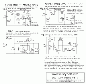
Choosing a MOSFET  The 2N7000 is a small signal, low power MOSFET in the standard TO-92 plastic package just like the other transistors commonly used for a JT.  Its pinout is also the same as the PN2222A or 2N4401: S G D which correspond to the emitter, base and collector of a regular BJT.  It has a Vgs(th) of 0.8V min, 2.1V typ, 3.0V max according to the specs. This is the threshold voltage at which the drain current becomes 1 milliamp. We can  see that this is above the 1.5V or less battery voltage of the conventional JT.  Something has to be done to get the 1.5V up to the 2 or more volts needed to fully turn on the 2N7000.  In the schematic, Fig.1 is the original circuit I devised to make the voltage high enough to drive the 2N7000’s gate.

How it works  The Q1, a puny 2N3904, is used as a conventional JT except it uses a much higher 10k resistor, which limits the current that Q1 can supply to the LED.  But this is enough to get the 3.3 or so volts across the LED, so the 3.3V goes back through the feedback winding and to the gate of Q2.  Notice that the current to the LED is rectified by the Schottly diode SD1, and filtered by C2. Some ‘experts’ claim that doing this makes the conventional JT more efficient, but I can’t see that because the rectifier drops a half volt, which is wasted power. But in this case it’s needed to boost the voltage to 3.3V. In Fig.4 I use the diode to rectify only the bias current going to Q1; the LED is driven directly by the drain of Q2 without rectified and filtered DC. The wasted power across the Schottky diode SD1 is eliminated.

In both circuits the smaller current from Q1 is increased greatly by Q2, which supplies most of the current to the LED.  This circuit works very well, but it is not as simple as the conventional JT.  If we just remove the 2N3904 and put a more powerful transistor in its place, we don’t need Q2 and other added parts.  What we really want to do is eliminate Q1 altogether. I thought about it, and all I had to do was come up with a way to get a few volts to bias the gate of the MOSFET close to its turn-on point.

A Simpler Circuit   At first I tried adding another AA cell to the existing one just to use for the gate.  It worked okay, so I checked the current of this second cell by temporarily putting a 100k resistor in series with the positive lead, but there was no voltage drop across the resistor.  Of course, because the gate of a MOSFET is just about an open circuit, it draws no current. Well, there is a small amount of current when the cell is connected, which is caused by the charging of the capacitance between the gate and source.  But after that, there is no measurable current flow.  The effective resistance of a MOSFET’s gate is a gazillion ohms. Actually, it’s something like thousands of megohms or more, but that’s so close to a gazillion ohms that it doesn’t matter (what is a gazillion anyway?).   So I removed the AA cell and put a 1.5V alkaline button cell in there. Same result: the circuit worked fine.  The current drain is so low that the cell should last as long as its shelf life, which today seems to be five or more years for a fresh battery. All I needed to do was order some button cell battery holders so I won’t have to solder to the button cells.  But some inventive experimenters I have seen made a holder out of a PC board and a piece of a paper clip.

Measuring LED Current  During these experiments I temporarily inserted a 1 ohm resistor in series with the LED as can be seen in the schematic.  I can monitor the current with this by putting the DMM set to its lowest voltage range, 200 millivolts, across the 1Ω resistor. (Hey, that’s cool!  I unhid the “Kitchen Sink”, which allows me to put special characters like the ohms “Ω” symbol into the text) If I measure 20 millivolts across the 1Ω resistor, then I’m getting 20 milliamps of current through the LED.

Other components

The 470pF capacitor C1 across R1 is there for a reason, I just don’t remember why. It could have been to make it start better with the much higher 10k resistor. The optional Cbyp is a bypass capacitor is an accepted industry practice, to prevent the cell’s internal resistance from making the circuit change frequency or whatever. It should work without it, most of the time.

The Toroid  In the schematic in a note I gave the windings for the toroid core. These are typical for a Fair-Rite 2673002402 core, wound with enameled wire.  These cores are called RFI/EMI suppressor sleeves, but they are the same size as a regular toroid core, and are available from Mouser for about a dozen cents apiece in small quantities. They work really well for conventional JTs and my Supercharged Joule Thief (see note below).

The LED  I’ve used both white and blue LEDs for most of my JTs.  I also bought a bunch of aqua colored LEDs which are the ones used for the LEDs in the green light of a traffic signal. These are very bright and have a forward voltage of about 2.8 volts. The size of the typical LED for a JT is the 5mm or T1-3/4 package. The reason is that a conventional JT on a fresh AA cell will put out about 60 to 70 milliwatts, which is just right for full brightness of a 5mm LED. I have used several other size LED, including the 10mm 1/2 watt 5 chip white LEDs, the 10mm 1W white LEDs, and the superflux or “spider” white LEDs, named for their four legged insect look. These are more powerful and require more current from the JT, in the case of 1 watt, that’s up to 300 milliamps.

Note:  I use four 18 inch (50cm) lengths of 30 AWG (.25mm) enameled wire wound onto the core at the same time, which is called quadrifilar or 4filar wound.  The number of turns is not critical and is usually around 25.  I use the DMM on low ohms or tone to isolate one of the windings, which becomes the feedback winding.  The other three windings are soldered together and become the primary winding. For the Fair-Rite 2673002402 core this gives about 400 uH per winding.  The 2643002402 core gives about 140 uH per winding. Both of these cores are inexpensive, small size, and make very good Joule Thief coils.

What the heck is this “þ” character?  Looks like a b and a p glued together!  Back to experimenting…
© RustyBolt.Info/wordpress
CyberChimps