default

2011-12-19 Low Quality Transistors, Counterfeit Transistors

Note: This blog uses some names of companies that are everyday names, and I am not implying that they have anything to do with anything illegal.  I do not imply and I do not make any claim that any company is doing or has done any of the things I talk about.

Many people get their components from local electronic stores and in the U.S.A. it seems the most popular store is Radio Shack (there seems to be as many RS stores as there are McDonalds).  Radio Shack might have sold “surplus” parts long go, but nowadays most of the parts they sell, especially silicon semiconductors such as transistors, are the same parts that are bought by the manufacturers of electronic equipment.  You or I can buy a thousand transistors from Arrow, Avnet, Digi-key, Mouser, Newark, Farnell, etc., and pay only 3 or 4 cents, or even less, apiece.  Radio Shack buys tens of thousands and packages them in packs of 2 or 3 and charges a couple dollars, and they are what they say they are, a 2N4401 for example.  But people like to buy a “bargain pack” of ten or more transistors for not much more than the cost of the 2 or 3 pack.  The transistors apparently are often marked with house numbers.

One weasel word I’ve seen used is 2N4401 Type transistor.  The word type implies that the transistors may be 2N4401 or a similar type, but not guaranteed to actually be that part number.  I say this because many or most times I see a project where the builder says the transistors are 2N2222, but the picture shows that transistor has a black plastic package.  The true 2N2222 or 2N2222A came in a metal package, and then later manufacturers put the same chip inside of a plastic package and called it a similar name such as PN2222 or MPS2222.  The only true 2N2222 comes in a metal package.  But buyers of those bargain packs that say the black plastic transistors are 2N2222 type are being misled.

Where do they get these transistors?   From manufacturers that had and order from a company that wanted their house number instead of the usual JEDEC (2N4401), ProElectron (BC337) or Japanese (2SC1815) part number?  Often a company may have had a contract or a production run that didn’t use all of the parts, so they try to get what they can by auctioning them off.  There are “grey market” parts  dealers that acquire these, and somehow they end up in the “bargain packs” that some electronics dealers sell.

One doesn’t know if these house numbered parts actually work like factory parts or if they are “outliers.”  For example, an equipment manufacturer has a Quality Control or QC department that receives all shipments of parts, and inspects them for quantity, quality, visually, etc.  If the parts are to be used in a piece of important equipment (such as a pacemaker) they may test each individual part, or they may selectively test a few of the parts and use statistics to arrive at a failure rate.

Another example is you look at the parts list for a piece of test equipment, you may see the house part number and in another column they give the nearest equivalent.  It may say “2N3055 specially selected”, which means, for example, that the company tested the transistor and found that even though the maximum rating of 60 volts was given in the data sheet, a high percentage of the 2N3055s would be 80 volts or more. So they select these and reject the ones lower than 80 volts and later these rejects get auctioned off to the “grey market” parts  dealers.  They still say they’re 2N3055, and they still meet the specifications given in the data sheet.  But some experimenters may have been using the 2N3055s that will handle 80 volts or more, and when they buy some of these rejected parts, the 2N3055s will not meet their expectations and will not handle any voltage above 80 volts.

Some “bargain packs” also include regular JEDEC etc., numbered parts just to make sure that the buyer doesn’t get a whole package of duds.  I have gone to the Radio Shack store and carefully looked at the transistors inside of their bargain packs.  The salesdroid has on occasion interrupted his cell phone sales pitch to a customer (gotta make some money with a commission sales) to come over when he saw me shaking the packs to see what was inside.  On occasion I found that some packs had several of certain transistors that I wanted.  But I think others had the same idea; I found that the packs had been picked over and no longer had what I wanted.

Sometimes the luck would run the other way.  I would check the bargain pack to make sure that the “2N4401 type” didn’t include the 2N3904 or BC547 transistors.  These may be NPN and work like a 2N4401 in some circuits, but they cannot handle as much current as a 2N4401. I could then avoid bargain packs that had these.  The reason I point this out is that the bargain packs have a wide variation on what the buyer is getting, and he might be fooled into getting something that is less than he expected.

The bargain pack of 20 transistors for three dollars amounts to 15 cents apiece, which is 3 or 4 times as much as the cost from a distributor.  I just stopped buying the Radio Shack parts and went on eBay to find what I needed.  Then I bid on and won “1000 transistors”, and when I received them, I found that the bag was smaller than another bag of 500 similar sized transistors.  I counted them by putting them into piles of ten each, and found that there were a total of 400 transistors.  I complained to the seller, who claimed he didn’t know (he must not be very observant), but settled by refunding me 60 percent of the cost.  I made eBay purchases of other used stuff, such as test equipment; more often than not I got less than I had expected and I came to the conclusion that many of the sellers on eBay were just as bad as some of the grey market sellers – or else they are, or they act like they don’t know anything about it, aka “plausible deniability”.  I stopped buying parts from eBay and have since been buying parts from the companies I mentioned earlier, and found that Mouser often had better prices.  But I have counted parts and found that they had shipped me parts short anywhere from 1 to a few dozen out of a hundred.  Often these were easy to count because they came on tape, so I wonder why they couldn’t make an accurate count.  Duh.  I still buy parts from them but I’m careful to count some to make sure I’m getting what I paid for.

I have a transistor tester that I can use to find out how well a transistor performs (inexpensive DMMs have a transistor checker, too). The tester shows that there may be a wide difference in the performance of the transistors in the bargain packs.  I cut off the lid of a corrugated cardboard box and slit it with a utility knife.  This left the corrugations exposed, so that each corrugation could hold a transistor or diode that I had tested and I could write on the cardboard what the test result was.  I also built a test jig with a transistor socket and rectified AC with a current limiting resistor, and jacks for my multimeter.  I could use this to measure the breakdown voltage of each transistor, up to the peak AC voltage, which is about 160 volts..

I also can see what’s going on in a circuit with an oscilloscope so I know what kind of transistors I’m getting and using. I have plenty of experience with issues caused by low quality and defective parts.  I should also add that sometimes it is easier and more productive if I do a repair by replacing most or all of the parts (this is known a shotgunning).  This is especially true with older equipment that may have a bad electrolytic capacitor.  If one went bad, it is likely that others are getting old and drying out and will soon go bad even if they haven’t already.

Fakes  And then there are those that sell counterfeit parts. Some unscrupulous dealer may remove the part number and replace it with the part number of a higher rated part and then sell it for more, making a lot of money.  Sometimes this happens because the manufacturer has discontinued making the part, and the grey market dealers have to fake the part.  I have read about this happening with the power transistors used in the output stages of high power audio amplifiers.

When I worked for a company that made test equipment, they received bad CMOS chips from a distributor.  We assembled the equipment and put the units into burn-in over the weekend. On Monday morning most of the units had failed because of one particular chip.  Those chips had to be removed and replaced.  But the problem was that CMOS chips were in so high a demand that they had a lead time of the better part of a year, so if the company ordered more chips when they found out they were bad, it would take longer than six months to receive replacements.  In other words, the company was having a difficult time getting the orders shipped and hence making the money they would otherwise make.  I learned that they had to back date some things, like a month suddenly had more than 31 days!  These fakes just show us that when there is a crooked way to make money, someone will find out and take advantage of other unfortunate suckers.

Back to experimenting…

default

2011-12-20 Joule Thief Mini Maglite

I recently found this article on how to convert a Mini Maglite to use a LED instead of the incandescent light, and the author does it by using a Joule Thief.  This has been an inspiration to me, because I have thought about converting several flashlights to LEDs or to a single battery but I have always found some difficult to surmount obstacles that prevent me from proceeding.  Another factor is that I usually (especially at this time of the year) give myself a gift of a couple new flashlights every year.

One obstacle I’ve always run into is the on/off switch, which in the case of the Mini Maglite, is different than other flashlights.  Most flashlights with a screw type switch tighten the threads to turn the switch on; the Mini Maglite tightens the threads to turn it off.

Brightness  He complains about the brightness saying that it is barely usable.  I agree that the 3mm LED may be blamed for much of the problem, but I think that a good part of the problem is the coil.  He said he used very fine wire, 40 AWG, which according to my wire table has about 1 ohm of DC resistance per foot.  If he used about a foot of wire to wind the coil, then the primary winding has about an ohm of resistance, and this is much too much resistance for a decently performing Joule Thief, and will also lower the efficiency, which he claimed was very low.  In the tiniest of the coils that I wind I use 30 AWG wire, which has 1/10 ohm per foot, and consequently would have 1/10 the amount of resistance in his coil, and also 1/10 the amount of losses and higher efficiency.  He mentions, but doesn’t give any details about changing the “transformer” (more on this here).

Transistor  The type of transistor used is very important.  He said he used the “PN222A” but I think he meant PN2222A, which is a better choice than the 2N3904 (but see my note below).  He didn’t say anything about the resistor he used, but the standard JT value is 1000 ohms or 1k.  One way to increase the output of the transistor is to decrease the value of the resistor.  Typical values are 820, 680 or 470 ohms, but I would use 470 and probably 680 only on depleted cells; the current would be too high on a fresh cell.

For getting more current out of a JT, some good choices for super beta transistors are 2SC2500(D), KSD5041, and NTE11.  Any of these will boost the output more than double, to the point where you must use more than 1 LED to prevent the LED from having excessive current.

Back to experimenting…

Note: This not became so long that I had to give it its own blog.

default

2011-12-18 WEB- 200 Volt Joule Thief

on December 18th, 2011 by - Comments Off on 2011-12-18 WEB- 200 Volt Joule Thief

My Watsonseblog dated 2011 Sep 18

2011 Sep 18 200 Volt Joule Thief


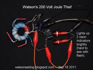
This turned out to be easier than I thought, since I was messing around with some serious voltages. It didn’t take long to wind the core, and I used some scraps of wire (you can see the splices I covered with red shrink tubing).

The core
I used a rather large 36mm or 1.4 inch OD core, and wound seven turns of red wire for the primary and three turns of white wire for the feedback windings (see picture). The core is high permeability and the primary winding was about 400 microhenrys. Starting at the collector end of the red winding, I connected some more 24 AWG insulated telephone wire and wound another 46 turns, splicing the wire as I went. Since the cold end of the high voltage winding is connected to the collector, the ratio of the windings is about 8 to 1.

I used a BAV21 high voltage diode to rectify the hot end of the winding, and I connected three 10 uF, 63VDC caps in series for an effective capacitance of 3.3 uF at 189VDC.

The joule thief part is the PN2222A transistor‘s collector connected to the red winding and the base connected to the white feedback winding through the 1k resistor. I put a 47 uF capacitor across the power supply leads.

Operation
After I got it together I connected the DC meter across the three caps and touched the 1.5VDC power supply leads briefly to the plus and minus, and the meter shot up to way over a hundred volts. Wow, I knew then I had to put a load across the three caps. I got the spiral part of a CFL and connected it across the three caps. I connected the power supply up, and I watched the meter zoom to over 200 volts, but the CFL refused to light up. Whew, the voltage was too high, the 3 poor capacitors were getting more than 70 volts apiece.

I removed the CFL and connected two neon panel indicators in series across the 3 capacitors. I reconnected the power supply and the voltage across the 3 caps and indicators stabilized at 136 volts and the neons lit up brightly. The 1.5V supply was at 55 milliamps and the frequency was 23 kHz. I’m disappointed that the CFL wouldn’t light up, and I may have to add more turns to see if I can get it to light.

Back to experimenting…


default

2011-12-17 LED Torch With Adjustable Brightness

Early on in my JT experiments I experimented with a pot (potentiometer) in place of a resistor, which was used as an adjustable resistor and allowed me to optimize that particular JT.  After the optimum setting was determined, the pot could be removed and replaced with a regular resistor.  It seemed that the pot was confined to use just for experimenting.  But at the same time I realized that using that same pot, a JT could be made to have adjustable brightness.  One problem was that the size of the pot was as big or bigger than the rest of the JT circuit, and pots are more expensive than a simple resistor.  One other thing I noticed: it seemed that no one else left the pot in for daily use.

Then I just came across this circuit that does use a pot to adjust the brightness.  Good to see someone else decided to make use of this pot for every day use. But why did the author contradict the design by adding a 39R resistor and the second BC547 transistor to limit the current?  He could have done the same thing with the 330 ohm resistor by using its value to limit the maximum current. The 330 ohms is low, it should be closer to 1000 ohms as used in a typical JT.

The BC337 is a very good choice for the JT transistor, but it has a self-imposed limit on the amount of current it can handle in a JT circuit.  Once the 330 ohm resistor has been set to give a maximum LED current of 20mA, then the second transistor is no longer needed. And along with that, the high speed diode, 100u filter cap and 39R resistor can go away.  All that’s really needed are the three LEDs across the BC337.

Oh, and another one of my humble opinions.  The high speed diode and 100u filter capacitor are not necessary and wasteful of power.  The 0.8V or more voltage drop across the diode, multiplied by 20 milliamps, equals 16 milliwatts of wasted power that could be better put to use making light in the LED.  When you think of the word diode, remember that the LED is already a light emitting diode.  So why would you want to add something you already have?

Last but not least, the three LEDs are connected in series.  With each (white) LED having a voltage drop of 3.3 volts, there is about ten volts total across these LEDs when they’re lit up brightly.  A normal 1 LED JT has to boost the voltage a bit more than twice (3.3V / 1.5V), but this JT has to boost the voltage 6.7 times.  This puts a much higher demand on the coil, which should be low loss and have low wire resistance.  The 35 turn primary winding should not be made of thin wire, it should have a resistance 1/4 ohm or less.

Needs More Power  Also, you must remember that this JT will not be able to light up the LEDs to full brightness.  Let’s do some simple math to see why.  The three LEDs require 10V total, at 20 milliamps for full brightness.  That is 200 milliwatts, or three times the power of a typical one LED JT.  Therefore the input current from the battery must be three times higher – a typical JT uses 80 milliamps, so this JT needs 240 milliamps.  The problem is that even as good as the BC337 is, it can’t handle that much current.  What this JT needs is either three transistors or a transistor that can handle three times the current.  Typical high current transistors are the KSD5041, ZTX651 or NTE11.  Or put three BC337s in parallel.  Just connect the emitters ans collectors of the three transistors together, and connect each base to its own 1k resistor, with the other ends of these resistors going to the feedback winding.

The coil has a feedback winding with 20 turns, which reduces the negative voltage that the transistor’s base to emitter junction has to handle, which is specified at 5V maximum in the datasheets.  But 20/35 times 10V is 5.7V, which is still somewhat over the maximum.  The feedback winding should have a few turns less, say about 17 or 16.

Obnoxious  I noticed whenever my mouse pointer went over one of the highlighted, underlined words in the text, it shot up a big advert for something totally unrelated to that word.  This is really obnoxious and it’s a shame that the blogger/blogspot (owned by Google) has to stoop so low to get people to see their ads.  I hope they end up in the same situation as AOL: no one wants to put up with this pestilence.

Back to experimenting…

default

2011-12-16 Phone Line Powered LED Light

This Instructable tells how to build a LED flashlight that is connected to and derives its power from the telephone line.  If you can’t take the time to read this, at least read the conclusion at the end.  First off, I must warn the reader that this is illegal, foolish, dangerous and can cause problems with the phone line.  The instructable has over 146 comments that people have written that tell various reasons that they believe it should or should not be used.  I will give a few true facts which may be disputed but are still true facts.

LEGAL  The federal Part 68 rules govern phone lines and say that connecting such devices to the phone line is not allowed.  Connecting a device that draws current from the phone line can cause the telephone company’s equipment to sense that there is leakage on the line, and cause the equipment to initiate a trouble alarm and can cause the line to be temporarily or permanently disabled.  The trouble alarm may cause the telephone company to dispatch a repairman to find the ‘leakage’, and when they find that it is caused by your light, they will bill you for the repair time.  In my area, this is about a hundred dollars for an hour.  I will be truthful and say that the telephone company may not do this, but may disable the line instead.  Here is a writeup about the Part 68 regulations.  This LED light violates the following rule (which is found in this link, and I quote verbatim):

Dc on-hook resistance is required to be greater than 5 megohms for an applied voltage of up to 100 V and greater than 30 kilohms for an applied voltage of up to 200 V (see Figure 3). The telephone companies use an automated insulation test system as part of their maintenance routine. If the dc on-hook resistance of an attached piece of equipment is too low, the line is interpreted as being damaged, and repair procedures are initiated. The dc resistance requirement prevents false service alarms.

SAFETY  The circuit uses a LM317 which is rated for a maximum of 35 volts.  The telephone line has voltages that range from 48 to 56 volts when the receiver is on hook, to 90 volts RMS or 150 volts peak during the time when the phone is ringing.  These far exceed the maximum for the LM317 and could cause it to overheat and burn out. The most unsafe time for a phone line is during a thunderstorm when a lightning strike even miles away can cause extremely high voltages and currents in the phone lines, and cause anything connected to it to catch fire.

Technical  This LED light is supposed to steal enough current from the phone line to light the LEDs but not enough to cause the equipment at the central office to sense that a phone is off hook and trying to make a call.  The LED current is supposed to be around ten milliamps, but this causes two problems.  When the CO (central office) senses the phone is on hook and ready to receive a call, the CO sends out a ringing current of 90V AC (RMS) which is supposed to cause the bells to ring.  But the LED light is loading down the line, and the ringing current goes into the light instead of the bells, and the bells ring weakly or not at all.

Another odd thing can happen during the time the ringer current is being sent.  While the ringer current is being sent, the CO equipment is sensing if the phone is picked up or goes off hook.  When the ringer current goes through the LEDs, the CO immediately senses that the phone is off hook. The ringer current is immediately stopped and the CO connects your line to the calling party.  But now the voltage is too low to keep the LEDs lit, so the current drops below that required to make the CO sense that the phone is off hook, and it immediately disconnects the call.  What the person calling your number hears is a very short ring, like a BRIP!, then nothing, and after ten or more seconds, he then hears dial tone, like the phone is ready for him to make a call.  In other words, it seems like the call didn’t go through.

Confusion  The LED light will not work when your telephone is off hook and making a call.  It will only work when the receiver is on hook or “hung up”.  Suppose you plug the light in and it works.  Then you take the receiver off hook to make a call.  Everything works okay, until you hang up the receiver.  As soon as you put the handset into the cradle, the switch disconnects the phone from the line.  The phone line starts to rise to its normal on hook voltage, 48 volts.  But the LEDs turn on before it gets to the full voltage.  The equipment in the central office can get confused and think the phone is still off hook and trying to make another call.  The equipment gets confused and tries to send dial tone, but the LEDs go out again.  So the cycle repeats on and off, and never does get to a stable state. I’ve seen this happen with some things I’ve connected to the phone line.

DSL Line  Your phone line also carries the DSL signal to give you your internet connection.  When you put this LED light on the line, it loads the line down so that your DSL modem receives a weak or no signal.  Don’t be surprised if your internet connection stops working when you put this light on the phone line.

Another Safety Issue  Many people nowadays have other services that furnish your telephone line service.  If your telephone line is furnished by your cable TV company, then the telephone line is connected to the cable coming into your house.  But the cable does not furnish your telephone with power.  The telephone line is typically connected to an adapter box that gets its power from the wall.  There is a small battery inside it that will keep it running for some time if the electric power goes out.  If you connect the LED light to your phone line, it is using the power from this battery when the power is out, and the battery will be dead much sooner and you will not be able to make a phone call during the power outage.

VOIP  Some people have switched from regular POTS (plain old telephone service) to VOIP (voice over IP).  This is where your telephone is connected through the internet, with adapters such as the magic jack.  The telephone line furnished DSL but there is no telephone dial tone and no telephone current.  So if you plug your LED light in, it will not light up.

Conclusion  I could go into more detail about this, but I’ve given enough reasons why this LED light is a really bad idea (I could comment about old rotary dial phones, but almost no one uses them today).  The 146 or more comments left by others show that many other people think that it is a really bad idea.  Don’t be foolish and attempt to build this project. You’re just wasting your time and taking risks that you shouldn’t take. Let some other fool make the mistake and when you read about it in the comments you can say, I’m glad I didn’t build this LED light.

Back to experimenting…

default

2011-12-15 Joule Thief Flasher, Various Types of

Or Flashing Joule Thief, or blinking Joule Thief, or 1.5V flasher or 1.5V flashing LED or low voltage LED flasher… I guess there could be a few more names that describe a family of circuits that use a single 1.5V cell, and flashes or blinks a LED.  I’ve found a few ways to do this on the web, and I’ve designed and built a few other circuits myself  to do this.

The single 1.5V cell creates limitations that make it necessary to increase or boost the voltage to that needed to light a red or orange LED, which is 2 volts, or about 3 volts for a blue or white LED.  One that works with a red LED is the voltage doubler circuit.  One way of V doubling is to switch a capacitor so that it is first charged in parallel with the 1.5V, then switched in series with the 1.5V cell to give a total of 3V.  The size in microfarads determines the amount of energy discharged into the LED and the brightness of the flash.  Cappels goes through some explanations of different versions of these.  These do not use an inductor; they are not a Joule Thief.  Cappels runs them at high speed so the LEDs look like they’re on steady but if the pulse rate is slowed down to less than 10 PPS then they will look like they’re flashing.  There is another similar flasher circuit on Dave Johnson’s Discover Circuits website, but his uses a CMOS chip to drive the .boost circuit.

Another very similar switched capacitor circuit could be found here, but when I tried it the browser just waited without timing out.  I just tried it again and it timed out within a half minute.  I searched the web for this and found references to the link I gave, but nowhere else.  I’ve built several of these, all without problems.  They draw very little power and the cell lasts for a long time. I have attached my drawing of the schematic to this blog. → → →

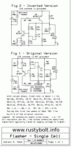
About the circuits that I’ve designed and built   I corresponded with Quantsuff and he came up with some flashers and I used a similar design that takes my Supercharged Joule Thief and adds a capacitor and resistor to cause it to flash.  The single transistor in the Supercharged Joule Thief does both functions of boosting the voltage and causing the circuit to flash.  One limitation with this circuit is that the flash starts to get longer as the battery voltage drops, until it just stays on solid as it gets down to 1 volt or so.  The great thing about the circuit is it is very simple, with just the resistor and capacitor added.

The Joule Thief does the voltage boost simply and easily.  Using the single transistor to do the voltage boost and flash the circuit puts added demands on the circuit so that interactions between the flashing and other circuit functions cause limitations.  I believe this is why the SJT flasher stops flashing and goes on solid at 1 or so volts.  In order to prevent this, I decided a better way to go would be to move the flasher function to a separate circuit and allow the Joule Thief circuit to perform its single function of voltage boost.

Blue Blinky  On Dec 1, 2007 I finished building and put a partly used AA cell into the circuit I came to call the Blue Blinky.  At the beginning of each month for 21 months I blogged that it was still running, blinking away on a desk.  It became much dimmer, but it was still going even though the cell’s voltage was down to below 0.8 volts.  The beginning flash rate was about 1.2 flashes per second.

Referring to the schematic and picture in the link above, the circuit consists of two parts. The left side of the schematic is the two transistor flasher which can be found on the web including here.  This circuit does not have to turn on and off the total Joule Thief current, it only handles the base bias current to the Joule Thief transistor.  This is just a milliamp or so, and the idle current between flashes is very low – which helps the battery last a long time.  The right side of the circuit is a conventional JT except the base bias resistor goes to the flasher circuit instead of the positive V.  The C5 bypasses the pulses of the feedback winding to negative and the R5 resistor quickly discharges C5 to end the pulse.

When the flasher circuit turns on, the voltage to the JT’s base bias resistor rises to nearly the full 1.5V, and the JT takes off pulsing the LED with the boosted voltage. During this pulse the battery current should be somewhere between 50 and 100 milliamps if the JT uses a 2N4401, PN2222A, BC337 or similar transistor.  This pulse gives a very bright flash of light, but is very short, only two to three milliseconds.  Then the flasher turns off, the circuit rests for almost a second, before flashing again.  I would guesstimate the off to on ratio is somewhere around 300 to 1, so the battery will last that many times longer than a Joule Thief that’s on steady.  If the Joule Thief circuit lights brightly for a few days on a fresh cell, then it should last a few years when flashing.

Astable Multivibrator flashes Joule Thief  This circuit is similar to the above circuit in that the flasher and Joule Thief are separate, but the flasher consists of two transistors in a simple astable multivibrator.  The astable mvbr circuit has two base bias resistors to positive, two collector load resistors to positive, and two timing capacitors each connecting the base of one transistor to the collector of the other transistor.  If the capacitors and base bias resistors are the same value, the ratio of on to off will be equal, the output will be a square wave.  But we want the circuit to put out a short pulse with a long time between pulses.  This requires that the capacitors and resistors be unequal so that the pulses are short.  But the circuit allows us to set the ratio of on to off times from equal to very unequal in any ratio.  Ten percent on, 90 percent off might be a valid choice.

I got around the 2V or more LED voltage problem by running the astable multivibrator at 1.5V, which works okay.  Then the output of this drives the 1k resistor of a Joule Thief, which boosts the 1.5V up to run the LED.  The flashes are very bright, but the battery life won’t be as long as the Blue Blinky flasher.  The typical battery life might be ten times longer than a constantly on Joule Thief.  I designed a circuit board and sent it out to ExpressPCB and got back three Miniboards each with 3 flashers.  I cut them up and assembled them and they work great.

Back to experimenting…

default

2011-12-14 VHS Powered Joule Thief

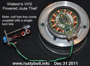
Not all of my many Joule Thiefs are powered by electrochemical means.  Some are powered by electromechanical devices.  This one is powered by the rotating head assembly of a VHS tape recorder.  As can be seen, the motor is a series of coils wound around an armature inside of the rotating magnet, which is attached to the rotating heads.  The assembly has enough mass so that a good spin with the fingers produces a bright light for about a second or two.

This motor reminds me of the motors I’ve seen in 5-1/4 inch floppy drives.  They have a similar armature that has wire wound around the legs, and the wire can be removed to make coils for JTs. This motor has just a few connections so it was easy to check them for continuity and then hook up the JT and see if it lit up when spun.  The windings of other motors may be connected differently than this one, but I have not seen any other VHS recorders.  All I know is that these are different than the windings of a hard disk drive,which seems to be typical of most brushless DC motors.

This Joule Thief was one where I experimented with the coil.  I used very small toroid cores, and I put the feedback winding on a separate core  and coupled the two cores together with a single turn link of heavy wire.  This works just fine. The two cores are electrically the same as one core.  This is the only JT core to which I’ve done this, probably because I haven’t though of any reason why it would be of benefit. But it does work okay.

I have built dozens of these electromechanically driven JTs, some with motors from hard disk drives, some with motors from floppy disk drives, and some with motors from CD-ROM drives.  Oh, yeah, I forgot about those motors I scrounged out of old inkjet printers.   They all generate low voltage, which the JT boosts and lights up the LED brightly.  Some motors don’t need the Joule Thief, they are capable of generating enough voltage to drive the LED directly.  The CD drives are fun because the motors are small and often come with a gear mechanism which can spin the motor fast enough to generate decent light.  Problem is that most of these motors have to be spun by hand, and it can get really boring really quick, especially when the shaft starts to cause your fingers to feel like they are going to be worn out.  In the case of this VHS motor, it’s really easy to spin and does a good job.

Back to experimenting.

default

2011-12-05 JouleThief Bias Boost

I’m working on this one.

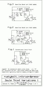
In Fig.1, there is a schematic of a conventional Joule Thief.  If the battery drops below 0.5V, the circuit will not start on its own because the battery voltage is less than the forward voltage of the base.

In Fig.2, the Bat22 provides about 33 microamps through R21 and R22a and R22b, through the base to forward bias it so the circuit will start up.  Once the circuit is running, the feedback winding has high enough voltage to keep the circuit running.  The Bat22 will continue to supply about 33 microamps to the circuit as long as it is running.  When the main Bat21 is switched off, the Bat22 should also be switched off.  But even with the 33 microamps continuous drain on Bat22, it should last for a very long time, several months or a year.

Update – One experimenter posted a video on Youtube of his circuit which used a high ratio between the windings on the toroid.  The feedback winding had several times – 5 or more times – the number of turns that the primary winding had.  The circuit would start at less than 0.4 volt, which is really low for a conventional JT.  It also had no resistor, or zero ohms resistor, which meant that when it had started, a slight increase in battery voltage would dramatically increase the battery current and LED brightness.

Experimenting…

default

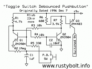
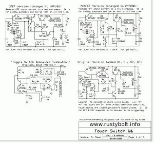
2011-12-12 Toggle Switch Debounced Pushbutton, Touch Switch

I posted this circuit to the ‘net a long time ago, and it hung around on various forums or websites for a long time.  I had it in watsonseblog but that’s no longer available.  So here it is, along with a few more touch switch type circuits.

It’s a flip-flop that it toggled by the absence or presence of charge on C1 when the P.B. pushbutton switch is pressed.  The C1 is slowly charged or discharged through R2 so you can press the button quickly and C1 will not yet be charged or dischaged and the circuit will not toggle.

The Q3 PNP transistor can deliver a hundred or so milliamps, enough to drive a relay.  If you use a relay, make sure to put a 1N4002 rectifier across the coil, with the cathode or banded end to the positive side. If you want more current, then a power transistor could be added to greatly increase the current.

Back to experimenting…

default

2011-12-10 Darlington Joule Thief – watsonseblog

The following is from a cached version of my late watsonseblog.

2011 Mar 15 Use Darlington for Joule Thief

An email correspondent asked me if I have ever used a Darlington for a Joule thief. The short answer is no. The longer answer involves some lengthy explanations below.

A Darlington pair connects two transistors so that their individual current gains are multiplied. If you have two transistors connected, each with a gain of 200, then the overall gain is 40000. Darlington transistors are available with two transistors in a single package, or you can connect them yourself. The single package Darlingtons may have gains of several tens of thousands. This gives the transistor some advantages. The current needed at the input is just microamps or even less. The input impedance is high. But along with this there are some serious disadvantages.

The most important issue is that the two base to emitter junctions are in series. Each junction has a forward voltage of about 0.6V. The total voltage is over 1 volt, typically 1.2 volts. In order to get the Darlington to conduct current, the base has to be 1.2 volts above the emitter, and in the case of a Joule thief this is more than the voltage across a used battery.

The other important issue is the collector voltage can never go below 0.6V because if it did there would then be too low a voltage across the second transistor’s base to emitter junction and it would not conduct. In the case of a Joule Thief with a battery voltage of 1.5V, this issue means that the Darlington pair would waste more than one third of the power.

The two issues above are not a problem when the supply voltage is more than several volts, such as in an audio amplifier. One minor issue is that due to the high impedance, the Darlington’s frequency response is not that high, but this is not an issue for a Joule Thief.  But the two issues above are unacceptable for the low voltage Joule Thief circuit.  This Youtube video explains it visually.

Sziklai Pair
One way to deal with one issue is to connect a PNP and an NPN transistor together to make a Sziklai pair, AKA complementary Darlington. This reduces the voltage drop across the input to 0.6V, but the emitter to collector voltage is still 0.6V minimum, making for power waste and low efficiency just like the Darlington. This too makes it unacceptable for a Joule Thief. Remember, we are trying to squeeze every last bit of energy from the battery and turn it into light, not waste it on heat.

Other Choices
The advantage of a Darlington pair’s very high current gain is not needed for the Joule thief. The circuit requires very low Vce(sat) – the collector to emitter saturation voltage -which the above pair configurations do not have. It also requires low Vce(sat) at high collector currents. There are several transistors that meet this requirement, so we do not have to consider using the above compound connected transistors.

If you take apart a disposable camera, you will find a flash unit that operates off a single AA cell. At one time this circuit used a 2SD965 (Japanese) transistor, but nowadays the typical flash unit may use an equivalent surface mount transistor. The 2SD965 is available from Fairchild Semi as the KSD965, but the Fairchild KSD5041 is a newer and just as good substitute. Both of these are capable of handling 5 Amps collector current, which is amazing for such a little transistor. Another similar transistor is the KSC2500(D) from Fairchild. All of the above are capable of 1 watt or less dissipation. If you want higher power, the KSD1273 from Fairchild will handle several watts depending on the heatsink. This is a Superbeta transistor, with a current gain of a thousand or more. It does not necessarily have super low Vce(sat) but for a Joule Thief it will put out quite a bit of power.

Also, the D suffix or other letter at the end of the transistor’s part number is usually (for Japanese transistors) the gain range. In the data sheet, there will be a footnote telling what those mean. The A, B, C, gain ranges may be overlapping but usually centered around three points, for example 120, 240, and 360.

Other Considerations
Back to the Joule Thief. When you run a JT on 1.5V, you are already asking the transistor to do a difficult job. Only 1.5 volts supply voltage, and a hundred milliamps or more means the DC resistance of the circuit has to be very low. But the JT gulps large slugs of current with each pulse, meaning that the transistor has to conduct two or three times that much current for brief periods. This means even lower DC resistance, down to 1 ohm or less. You must minimize losses in the transistor, and in the coil primary winding by using wire that is heavy enough to have low voltage drop – a small fraction of an ohm. Success here shows up as low losses and higher efficiency. But remember that the typical JT has only about 50 percent efficiency. That is why I like my Supercharged Joule Thief (See Fig. 2 here this link no longer works, instead, use this link).

Now, when the battery runs down, or you run the JT from a lower voltage power supply, things are even more difficult. If you use a 0.5 volt solar cell, the voltage is one third that of a AA cell. The lower voltage means that three times as much current is needed to give the same power. And the DC resistance of the circuit must be NINE times lower. This means it must be a small fraction of an ohm. Things become critical, such as the resistance of the wiring on the circuit board.

More on this in another blog.  Also go check out the Wikipedia article for a more comprehensive explanation.

© RustyBolt.Info/wordpress
CyberChimps