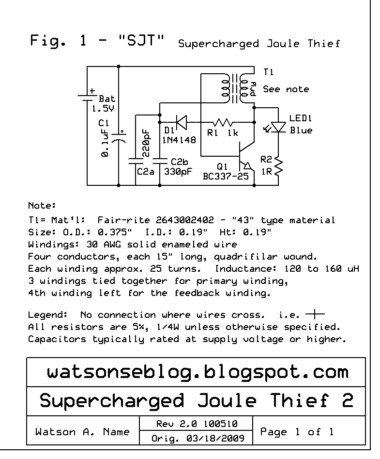
 My Joule Thief Plus or JT+ circuit uses an idea similar to that used in my Supercharged Joule Thief (SJT). My motivation for designing this circuit was the situation faced by the experimenter when s/he wants to drive a high power LED using a 1.5V supply. The conventional JT runs into a major brick wall when it is modified to put out more power. The transistor is pushed well beyond its limits when the supply current increases and approaches 1 amp or more. The DC resistances and impedances become so low that a fraction of an ohm resistance in the coil winding, for instance, becomes a major factor in limiting the performance and efficiency.
To get around this, I tried to use a power transistor such as the TIP41 for the high current JT. But the TIP41 has a very low current gain, around 30 to 50, which is less than a quarter of the typical PN2222A or similar small signal transistor. The first thing that many experimenters think of to solve low gain is to put a Darlington power transistor in the circuit. WHOA! let´s look more closely at Darlingtons.
Darlington Characteristics
 The Darlington is really two transistors compound connected, so the emitter of the first one feeds the base of the second one. We can see that the base current passes through the first base to emitter junction, then passes through the second base to emitter junction. We have two junctions connected in series, each having a voltage drop of at least 0.6 volt, for a total of 1.2 volts. This is nearly as much as the 1.5V battery supply! This severely limits the performance of the Darlington. Also, because the base current for the second transistor is supplied from the collector, the collector must be at least .6V for the second transistor to conduct. Therefor the minimum collector voltage for a Darlington is .6V, which is more than 1/3 of the 1.5V battery supply voltage and thus severely reduces the efficiency of the circuit. These limitations make the Darlington a very, very poor choice for a Joule Thief.
But we still need additional current gain to compensate for the TIP41s low current. We can get this by compound connecting the two transistors, but feeding the collectors separately. The higher drive voltage we need will then be derived from a separate power supply (see the following explanation).
(not so) Brief Explanation of operation
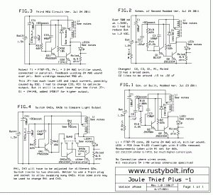
Refer to Fig.1 in the schematic. Like the SJT, this circuit takes some of the output and rectifies it to DC, which I call DC Boost. This is used to supply the base bias for the power transistor Q2. This bias current passes through Q1 which is switched by the feedback winding. At powerup, there is no DC Boost, so I added R2 which gives enough forward bias to Q2 to get the circuit started up and running and generate the DC Boost.
As I mentioned, this higher DC supply voltage solves the problem of low voltage and consequently low current for driving the Q2 power transistor. One theory that I’ve come up with is that if the power transistor requires a significant amount of current to drive its base, then this takes away from the current that would otherwise go to the LED. This diversion causes a loss of efficiency, and is something that should be minimized. Changing from the TIP41 to the 2334 is a definite step in this direction.
The values of some parts, similar to the SJT, are sensitive because they work best at the switching frequency to boost the output. If the parts values are less or more, they are not optimum for that frequency. With some experimentation I found that I could optimize the values by putting a potentiometer or variable capacitor in temporarily and adjust it for the best performance.
Other components The 1 ohm Rcled resistor is temporarily installed to monitor the LED current. If I measure 100 millliivolts with the DMM, then there is 100 milliamps flowing through the LED. Later I changed it to 1/2 ohm because the 1 ohm had too much voltage drop across it. With 50 millivolts across the 0.5 ohm, and 100 milliamps through it, there is still a lot of v drop; it would be best if the drop stayed well below 50 mV. A 0.1 ohm resistor would take care of that.
Transistor type For the first two figures I used the 2SC2334 for the output transistor. It drew over a half amp but the power supply only puts out a half amp, so the output voltage dropped. I reset it for 1.2 volts output so the power supply wouldn’t current limit. I will have to add that the C2334 (that’s what it says on the case) is the highest of the three gain ranges, 100 to 200. This is at least 5 times higher than the TIP41 and it really shows in the performance.
The circuit with the TIP41C gave much lower LED current and drew much less supply current. I believe that was because the voltage across the TIP41 is so low, it has even lower current gain than the 30 to 50 given in the datasheet. I believe this because it has a very difficult time delivering the high current at low voltage needed to put out several hundred milliamps to the LED. When I pull the TIP41 out and put in the C2334, the LED current is much higher and performance is much better. To show the difference I connected the bases and collectors of both the TIP41 and C2334 to the contacts of a switch. I can select one or the other and compare the difference. And there is a big, big difference. Once I saw how much better the C2334 performed, I will never, ever go back to the TIP41 for any Joule Thief.
In the first version (Fig.1) I used a 2N3904 for Q1. These cannot handle high peak current, so I ‘upgraded’ to a PN2222A or BC337-25. I did not notice any change with the C2334. The TIP41 did not benefit from the change.
Back to experimenting…


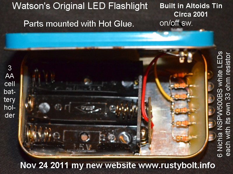 Back in 2000 and 2001, Californians faced an electricity shortage crisis caused by market manipulations by companies the likes of Enron that stole tens of billions of dollars from Californians. The electric companies implemented rolling scheduled blackouts to prevent unexpected outages. During that time, many people were afraid of being caught in a dark place such as an elevator without any source of light. I often carried a Mini Maglite but I wanted a flashlight (AKA torch) that didn´t have an unreliable incandescent bulb that would often burn out.