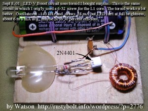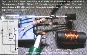
 I started experimenting with the LED V boost circuit, which later became popularly known as the Joule Thief. This pic, dated Sept 2001, is a not so good example. I used 36 AWG wire, which is too thin and has too high resistance; that’s why it was drawing only 19 mA current from the battery – it should be 70 to 80 mA. I made a mistake in the schematic – it shows a 10k resistor, which should be 1k.
The ferrite core had lots of turns of wire, but because it was very low permeability, the frequency was very high, 190kHz. A typical JT today would have 25 turns max and a frequency of less than 100kHz. I doesn’t have to be a toroid, though, but a toroid is convenient.
A few days later I changed the coil to a low permeability toroid, but again I used a lot of turns of too small wire. I hot glued the circuit to a piece of thin plywood so I could keep the coil wires from being pulled loose.
Posted Aug 14, 2012. Back to experimenting…