default

2012-05-27Ginormous Coil Voltage Booster

on May 27th, 2012 by - Comments Off on 2012-05-27Ginormous Coil Voltage Booster

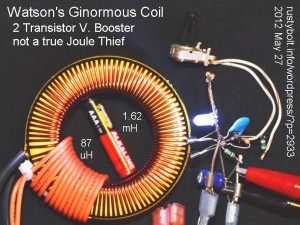
Well, I’ve finally got one of the coils I got from BG Micro hooked up to a two transistor voltage boost circuit (not a true Joule Thief) to see how well it works. The price was reasonable – a penny more than two bucks.

It’s drawing about 65 milliamps from the 1.5V supply, and putting out about 16 milliamps to the LED.  The frequency was about 35 kHz, but it seemed to drift a lot.  As can be seen in the picture, the coil is absurdly huge; the AAA cell fits nicely inside of the hole.  The winding that’s orange insulated wire is 87 microhenrys and the ‘main’ winding of magnet wire is 1.62 millihenrys.  It worked okay on both windings.

The beast is very heavy: 617 grams or about a pound and 6 ounces.  The weight leads me to believe that maybe the core is actually iron or alloy.  But then the copper wire is heavy, and may be the reason why it seems to weigh more than what a ferrite core that size should weigh.  However this is the first time I’ve picked up a core as large as this one, so maybe it’s all in my imagination.
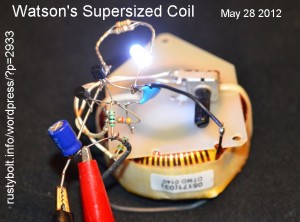
I still have to try out the other toroid core I got from BG Micro.  It’s not quite as big, but it’s still huge by comparison to the others I’ve been using for JTs.  Their ad says the PC board ‘insulator’ is attached with wire ties, but that doesn’t tell the whole story.  The coil is also glued to the board with epoxy, which can be seen in their picture.  It will take a lot more than just cutting the wire ties to get the board to come off.

I connected this coil up to the same circuit that I used for the other coil.  It works just about the same (see the picture).  It’s also heavy for its size, 327 grams or 11.5 ounces.

If you need some big toroids for your experiments, BG Micro is the place to get them – the prices are right.  But don’t expect them to be available forever, because these surplus places get a load of unique parts, and when they’re gone, they probably will never have them again.

Back to experimenting…

default

2012-05-25 Toroids Wound on Fair-Rite Cores

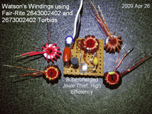
Here’s a picture I posted to my watsonseblog in 2009.  It shows several of the toroids I wound on Fair-Rite “suppressor sleeves” I bought from Mouser.com (They cost about 12 cents apiece).  The part numbers are 2673002402 (high permeability) and 2643002402 medium-high permeability).

default

2012-05-24 Pic of Supercharged Joule Thief From 2009 watsonseblog

on May 24th, 2012 by - Comments Off on 2012-05-24 Pic of Supercharged Joule Thief From 2009 watsonseblog

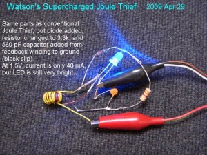
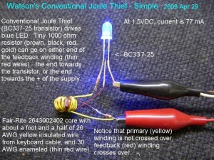
Here’s 2 pictures I posted to my watsonseblog in 2009.  They’re a picture of a conventional Joule Thief, and one of my Supercharged Joule Thiefs that I built to make sure that the first one or two were not just accidentally ‘too good to be true’.  The Supercharged Joule Thiefs worked so well that at first I thought it was just a fluke.  But they all performed much, much better than the conventional JT. You can see the schematic and data here.

SJT Circuit Description

The circuit is not complicated, almost as simple as the conventional JT.  The resistor is a 3.3k, but most of my SJTs use a 1.5k resistor, which gives about the same amount of light as a conventional JT.  This resistor depends on the gain of the transistor and how much light you want from the LED.

The transistor is a BC337-25, which has its printed face towards you.  For the PN2222A, 2N4401, etc., the face would be away from you.  The diode is an old germanium type, which works okay.  Just about any diode will work: 1N4148, 1N914, 1N5817 Schottky diode, or even the base to collector junction of a transistor.  The cathode or banded end is on the right.

The capacitor shown is a “561” or 560 picofarad ceramic disk capacitor.  A 680, 820, or 1000 pF capacitor will also work, with 680 probably the best choice.  Any type should work, plastic, ceramic or whatever.

Conventional JT

I may have posted these pics earlier.  I hope not.  So many blogs, not enough time to index them in a list.  I did that with my watsonseblog, then it was removed and all that work was gone and wasted.


default

2012-05-23 Sources for Wire, Toroid Cores

on May 23rd, 2012 by - Comments Off on 2012-05-23 Sources for Wire, Toroid Cores

Here’s a picture that I originally posted to my watsonseblog back in 2009.  It shows several ways to scrounge wire, and also a toroid core from a mouse cable.

The plastic and cable have to be removed from the core before it can be used.  The easiest way that I’ve found to do it is to heat the whole thing up with a propane torch.  The ferrite core is made from a glass like material and will not melt at red hot temperatures.

If I’ve blogged this pic before, forgive me for forgetting.  I’m trying to clean out my directory of old pictures by uploading them to the blog before I delete them.  I’m hoping my backups of the blog are good, because I may not have any other copies of the pictures.

default

2012-05-22 Dual Blinky

on May 22nd, 2012 by - Comments Off on 2012-05-22 Dual Blinky

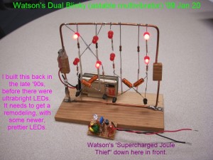
I took this pic in Jan 2009, and put it in my watsonseblog at about the same time.  It’s just two astable multivibrators suspended in a wire frame for support.  Since then I’ve replaced some of the LEDs with more modern high brightness green LEDs.

default

2012-05-21 ‘Toroid Free’ Air Core Joule thief

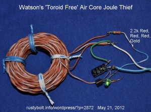
We don’t need no stinkin’ toroids!  Just wind 15 to 20 feet of twisted pair (this wire was from cat5e cable) onto something round, like a C or AA cell.  Then slide it off and tie it up in 3 or 4 places with some thread, twine, dental floss, piece of wire, or tape.  The inductance is under 100 microhenrys but it works okay.

The typical cat5e cable uses 23 AWG solid conductor wire, which has about 20 milliohms per foot.  Fifteen feet adds up to about 300 milliohms, or a little less than a third of an ohm.  That’s not too high for a JT, but I prefer to keep it to less than 1/4 ohm.  Lower resistance means less losses and higher efficiency.

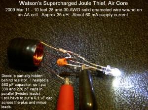
This is a picture of a Supercharged Joule Thief taken in March, 2009.  It also uses an air core coil.  With the lower inductance, the SJT can run at much higher frequencies, close to or in the AM broadcast band.  It’s a good idea to check to make sure your SJT isn’t broadcasting in the AM band.

Back to experimenting…

default

2012-05-19 Homemade Battery Holders

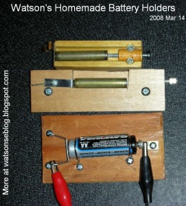
A picture of some homemade battery holders, once blogged on my old watsonseblog.  These have contacts that can survive alkaline corrosion and be replaced.

default

2012-05-18 Watson’s Tiny Toroid Joule Thief

on May 18th, 2012 by - Comments Off on 2012-05-18 Watson’s Tiny Toroid Joule Thief

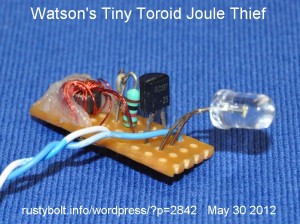
I had hundreds of pictures in my old watsonseblog blog, which went away when the blog was removed.  I’ve probably got the pics somewhere in the thousands of digital pictures that I’ve taken, but I haven’t got the time or inclination to go back through all of the pics to find them.  So I just pull out one of those old circuits and take another pic of it – it only takes a few minutes.

This one was probably before 2011, maybe 2010, when I found some of those tiny toroids at surplussales.com (it’s the T231212T).  The core is less than 1/4 inch or 6 mm O.D.  They have a high permeability and work well for making a really small JT.  And they’re inexpensive, about a quarter apiece.  I wound this one trifilar, with three strands of 30 AWG (.25mm) enameled, and put two of the windings in parallel for the primary winding.   I think the wire length was about 7 inches or so.

The perforated circuit  board is 1 inch (25mm) long by 7/16 inch (11mm) wide.  This one is quite a contrast to the big monster toroids I blogged recently.

Back to experimenting…

default

2012-05-17 DC-DC Converter and Meter on eBay

on May 17th, 2012 by - Comments Off on 2012-05-17 DC-DC Converter and Meter on eBay

Quantsuff says he’s getting one of these DC to DC buck converters combined with a meter, from a vendor on eBay named Kuuco (this link may go dead after a time, so do a search for “4.5-24V to 1-20V 2A Voltage Regulator DC Buck Converter Voltmeter Ammeter Blue”.  What I think is a stinking shame is that the meter has two digits after the decimal point, but they waste the rightmost digit with a letter U or V depending on your country leaving a single digit.  My ancient Weston analog ‘wiggle stick’ meter that I blogged several days ago has better accuracy than this.

A typical digital multimeter costing only a few dollars has a 200 millivolt range, and the higher voltage ranges are created by putting resistors on the input to make a voltage divider. So if the meter displays 0 to 2 volts, then it has a 10 to 1 voltage divider on the input.  If this converter / meter is displaying 0.1 to 20 volts in 1/10 volt steps, then it most likely has a 100 to 1 divider on its input.  What I would try to do is put another ‘shunt’ resistor in parallel with the divider resistor to make the range 10 to 1, so it would display 0.01 to 2 volts in .01 V steps.  When the output voltage exceeds 2 volts, it would display blinking 1s, or overrange.  I suppose a switch could be put in series with the shunt resistor so both 2V and 20V ranges may be selected.

The only thing that would have to be jiggered is the decimal point, which would be in the wrong place when the range switch is switched.  The decimal point could be blacked out with a tiny piece of black electrical tape.  Or if there is circuitry on the board for moving the decimal point, then it might be possible to add that to the switch I discussed above.  But even if this range is added to the meter, it still can only resolve down to 1/100 of a volt, and that cheap DMM can do at least ten times better.  This leads me to seriously consider taking a cheap DMM and gutting it, removing the case, and just use the board and the two sets of resistors needed to give the 2V and 20V ranges.  The only problem is that I would have to come up with an 9 volt supply that is isolated from the common of the converter.

I got the Harbor Freight flyer the other day, and it had a coupon for a FREE Centech DMM with any purchase.  I could walk in and buy a fifty cent key ring and walk out with it and the meter.  Really.

I reread the info at the bottom of the eBay auction I linked to in the first sentence.  The buttons select V or A etc, which seems to me that there may be a microcontroller on the PC board.  If so, then my guess is that it and its software determine how the meter works.  If that’s the case, then why does there seem to be a limitation on reading only a single digit after the decimal point?  Is it because of the way that the microcontroller handles the analog input? In any case, the point I’d like to make is that the software might be modified to take advantage of the second digit after the decimal point.

One thing I’d like to delve into is window comparators.  If a supply is typically mostly set at one or a few voltage points, then a window comparator could be used to do the setting. The idea here is to add to the power supply a circuit that is compact and small, simple, and draws little power.  This circuit will then eliminate the need for using a DMM to accurately set the voltage most of the time.

Using a dual opamp or comparator chip, the window comparator can tell when an input is between two voltage points, and if those points are within a narrow range, it makes it capable of setting a power supply to a certain voltage.  The circuit needs a stable reference voltage,  The window comparator’s output is a simple Go-No-go indicator such as a LED.  A switch can be used to change between 2 or 3 set points, such a 1 volt, 1.25 volt, and 1.5 volt.

default

2012-05-16 Big Cheap Toroids

on May 16th, 2012 by - Comments Off on 2012-05-16 Big Cheap Toroids

I found some large toroids (about 2 to 2.5 inch and about $2 something apiece) at BG Micro, so I ordered forty some dollars worth.  They must be heavy, ‘cuz the UPS charges were nearly half the price of the order!  I’m gonna wind some heavy duty Joule Thiefs or something like that.  Maybe make a CFL tube driver.  Still, they’re cheaper than other places.

More about these toroids and how I connected them up to a V boost circuit in my blog here.

© RustyBolt.Info/wordpress
CyberChimps