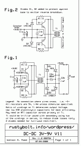
 I drew this up back in 2000 when I was developing a converter to run a 9V transistor radio from 2.4 to 3V. I decided that 9V batteries were too expensive and it would be better to make an efficient converter that would use AA cells or rechargeable AA cells. The converters worked for the FM band but caused a lot of RF interference on the AM band.
In Fig.1 the 1k resistors are connected from the base of one transistor to the collector of the other transistor. This uses the inverted signal on the opposite end of the transformer’s primary as the feedback, to keep the transistors oscillating. Since the primary winding is center tapped, the opposite end of the winding has the supply voltage with the opposite polarity AC voltage on it. In other words, if the Q1 collector has just switched off, then the voltage rises to 6V.