default

2012-06-18 Joule Thief as Light Organ

In this Youtube video, the experimenter connects the Joule Thief to the audio output of an amplifier, and lights a string of LEDs.  About the only thing new about this is the source of power: the amplifier.  I would say that it’s less than desirable to use the amplifier for power for the obvious reason that it takes away from the power to the speakers.  But assuming there’s enough power, using the amplifier’s power is a novel idea.  Apparently the audio output is not rectified or filtered; the AC signal is directly applied to the JT.  This eliminates the 0.8 volt loss across the rectifier diode.

Since the Joule Thief is not very efficient, about half the power is wasted, so if the LEDs get a half watt of power, the JT is using about 1 watt total.  This leads me to conclude that it would be more efficient to use a transformer instead of a JT to increase the voltage enough to drive the LEDs.  The audio signal is AC, so it is exactly what is needed to drive a transformer, which is far more efficient than the JT.  The transformer could be a regular power transformer with a 12 volt AC secondary, but with the audio connected to the secondary, and the LEDs connected to the power line side.

One problem with the use of the audio as power is that the volume control has to be turned up to high volume before there is enough to power the LEDs.  This applies to the JT as well as the transformer.  A potentiometer could be used between the amp and speaker to reduce the volume, but the pot must be high power to handle the power going to the speaker.

Unfortunately his all-nighter has caused a number of mistakes.  The 2N4401 is a NPN transistor, not a PNP.  But the schematic is drawn as if the transistor is a PNP.  It is very difficult to determine many of the parts in the schematic because of the blurring caused by wild camera swerving and gyrations.  I should mention that he’s pointing at something on the schematic and that point on the schematic isn’t even in the picture (I think he could have used a bit of sleep before he did this video).   Also, it’s the first rule of Joule Thief experimentation that you should never remove the LED when the JT has power applied.  Always remove the battery before removing the LED, or you risk damaging the transistor.

default

2012-06-17 Joule Thief As “Radiant” Charger

on June 17th, 2012 by - Comments Off on 2012-06-17 Joule Thief As “Radiant” Charger

I’ve read quite a few of the blog posts (here is one) and seen quite a few of the Youtube videos that use a JT for a charger.  Basically it’s a regular JT, with a diode from the collector to the charging battery’s positive terminal, and the other negative terminal connected to the positive of the running battery that is also connected to the coil.

When the coil is wound bifilar, the same voltage appears at both windings because the windings are equal in turns.  So if you get a high collector voltage, the voltage will be high at the winding that goes to the base bias resistor and pot, and then to the base.  But a high voltage is not needed at the base, it is turned on by current, and needs only a fraction of a volt to a few volts.

The usual circuit uses a resistor and potentiometer between this winding and the base to adjust the current.  But the resistor and pot are dissipating power that could otherwise be used in charging the battery.  Also, the base to emitter junction has a maximum reverse voltage of 5 volts, and it is bad for the transistor if the voltage goes more negative than this.

To ‘harvest’ this wasted power, the feedback winding (that goes to the pot. resistor and base) should be more closely matched to the current needs of the base.  This is easy to do, by reducing the number of turns so that the winding puts out lower voltage and the current stays the same, which means the total power used by the resistor, pot and base is reduced.  Less power is then wasted.   The pot will have to be set at a lower point, but the wasted power will then be available for the charging.

The feedback winding’s  lower voltage means that the base will not be exposed to high reverse voltage, and the transistor will have less risk of being damaged.  The next question is how many turns do we have to remove to get the voltage down to what it should be.

If a 12V battery is being charged, the actual voltage will be 13.8V, but the charger will have to put out more like 15 or 16 volts.  So the feedback winding should have no more than 5 volts.  This is about 1/3 of the output, so the winding should have 1/3 of the number of turns.  It would not hurt to have 1/4 the number of turns because you can adjust the pot to compensate.  Oops, I forgot to include the running battery’s voltage – the two are in series, so the collector voltage is more like 28 to 32 volts.  So the ratio should be more like 6 to 8 turns for the primary winding for every one turn of the feedback winding.

I have often seen this circuit built with a 1N4004 diode for the rectifier.   The 1N4004 series of rectifiers were made to be used at power line frequencies; when they are used in a high frequency circuit such as a Joule Thief, they cannot recover quickly enough and power is wasted in heating up the diode.  It is better to use a fast recovery diode such as the UF4007, or a 1 amp Schottky diode that can handle at least 100 volts.

If for some reason the circuit is running and the battery being charged is disconnected, the output voltage can go much higher.  That’s why the experimenters put a neon lamp across the transistor, to protect it from high voltage.  But the base will still get a voltage more negative than minus 5V.  So a good way to protect the base is to put a LED between the base and emitter, with the cathode or flat spot toward the base.  If the voltage goes more than 3V negative, the LED will light up and shunt the current away from the base.  Blue is a cool color to use. 😉

Back to experimenting…

default

2012-06-16 My House Pictures


My house pictures.


default

2012-06-15 8 LED Altoids Tin Light

I managed to squeeze 8 LEDs into holes on the end of the Altoids tin.  The brightness is truly awesome.  With that much battery current, I could have reduced the 33 ohm resistors a bit.  But why push it and waste more battery current?  It’s already really bright.  That’s why I put the second switch in there: to cut the brightness in half and save the batteries.  Actually, I probably could have arranged the switches so that “low beam” was just three LEDs, and then high beam would add the remaining five LEDs.  Or maybe even two and six.  Or I could’ve switched resistors in and out to vary the brightness.  But as it is, it works very well, and is easy to build.  The hardest part is drilling the holes and filing them to align them and get the hole for the switch square.  But that can be fixed by using a round switch.  I cut off the switch’s bat handle slightly to keep it from snagging on things and turning on.

default

2012-06-14 New Look???

on June 14th, 2012 by - Comments Off on 2012-06-14 New Look???

Can someone explain to me how a sheet of blank paper can have a “New Look!”

default

2012-06-13 Supercharged Joule Thief – Flagiusz Opinion

The following discussion is in regards to the schematic in my Supercharged Joule Thief blog dated 2011-12-04.  Flagiusz had some different ideas as to how it works.  I would like to say that I totally respect his opinions, but I have no way of offering a firm explanation of how it works because I have not taken the time to do any analysis of the circuit, only my observations during my experiments with more than a dozen that I’ve built (I can only say that the circuits all work consistently and very well, and have no quirks that would cause it to give unusual results).  The measurements (taken with a luxmeter) that I included in the schematic show that it is much more efficient than a conventional JT.

Some points in his opinion that I  would like to discuss follow.

Flagiusz believes that C2 speeds up the switching of the B to E junction.

The C2 value was chosen because it seems to be a good optimum point.  If I went below 500 pF or over 1000 pF, the output would drop. Flagiusz believes that it should be close to the B to E junction capacitance.  As far as I know, most small signal transistors have a junction capacitance somewhere around 10 pF.  The value of C2 is between 50 and 100 times that amount, so it is much greater than the junction capacitance.

As I said above, if I reduce it to only 10 pF, the LED’s light output  would drop to a much lower value.  So I think there is much more to this than speeding up the switching of the B to E junction.

When the switch is switched to the conventional JT, the switching rate might be around 80 kHz.  When the switch is switched to the Supercharged JT, the switching rate might be 240 kHz, or three  times as fast.  I don’t think that if a small capacitor was speeding up the B to E junction switching time, it would make this great a difference in the switching rate.

I think (but haven’t confirmed) that the C2 capacitor interacts with the feedback winding to become a series tuned circuit.  Series tuned circuits have the broad peak like the Supercharged JT has.

I have confirmed what others have said about rectifying and filtering the JT output before it gets to the LED.  This makes the LED brighter with no increase of battery current.  But there is a half volt or more drop across the rectifying diode, and this wastes several tens of milliwatts.  When designing the Supercharged JT, my intention was to eliminate this high LED current from the rectifying diode, so the power was not wasted.  The Supercharged JT accomplishes this very effectively.

I have not tried Flagiusz’ suggestion to use the conventional JT with the C2 similarly connected.  So I do not know if it works better, worse or equally well compared the Supercharged JT.

default

2012-06-12 Peter’s Joule Thief With Flip-Flop Project

on June 12th, 2012 by - Comments Off on 2012-06-12 Peter’s Joule Thief With Flip-Flop Project

Peter asked in an email what I thought about the schematic he gave a link to in his email.  With his permission I’m quoting his email:

I found this on Youtube: http://www.youtube.com/watch?v=xO0V6foiiy4
I wanna build this (or something like this) as a surprise gift for my wife – the schematic is here: http://i123.photobucket.com/albums/o298/RODALCO/Joulethiefwithflipflop.gif
May I beg you to give me your opinion on this? I think the transistors should be changed but I´m not exactly an expert on things like that!! Or maybe you´ve got somehing better than this – I searched your blog but didn´t find a “Joulethiefwithflipflop”.

I get Google Alerts and I recently received one for this Youtube video.  As he says in the video, it’s an astable multivibrator.  A flip-flop doesn’t oscillate by itself.  If you watch the video, you will see that the two LEDs speed up, then they both go on.  He doesn’t say what he’s doing, but I have seen this effect with astable mvbrs when the supply voltage drops too low.  I think this is the real challenge, and I’ll try to explain why.

The Joule Thief is optimized to put out the maximum current to the LED when the battery voltage is 1.5V.  When the cell’s voltage drops down to 1.2 volts, for example, the LED current drops a lot more, and the LED may have much less current than at 1.5V.  The current may drop by more than 1/3.

When the Joule Thief’s output is rectified and filtered, as it is in the schematic, the DC power output will also drop by a large amount as the cell voltage drops.  But the astable mvbr needs enough current to keep it running, since it’s a load that does not change.  The Joule Thief’s output voltage drops to reduce the current it has to supply, and soon the astable’s flash rate increases as it becomes current starved.  Then the LEDs both come on when the astable can no longer sustain oscillation.

One way to solve this is to design the Joule Thief to put out enough power at a lower voltage, 1 volt for example.  But then the Joule Thief will draw excessive current at 1.5V.  What has to be added is a circuit that starts to take effect when the cell voltage rises above 1 volt.  At higher cell voltage, the circuit turns on and shunts the base bias current from the Joule Thief’s 1k resistor.  As the cell voltage drops, this shunting is reduced and the Joule Thief keeps putting out nearly the same current.

In order to get the Joule Thief to put out enough at 1V cell voltage, the 1k base bias resistor must be reduced.  The lower value depends on the transistor, but I would guess 470 ohms or even less.  And the transistor must be a much better choice than the BC547, which can’t do the job at 1.5V.  I would try a BC337-40 as a starting point.

Next is the voltage, current and power demands of the astable itself.  You will notice in the schematic there are two resistors, each 560 ohms and each in series with the LED.  These resistors cause a voltage drop, and waste power.  It would be better if we could reduce their value a lot, or even eliminate them (zero ohms).  But the astable needs some resistance to develop some voltage so the capacitors will feed back some voltage to keep the circuit oscillating. I do this by putting a resistor across the LED.  I have not found any information on what this resistance should be, but I use a value that is 1/10 of the base bias resistor.  If the base bias resistor is 47k, for example, then I use 4.7k.

More to come.

default

2012-06-11 Watson’s Salvaged CFL Toroid Cores

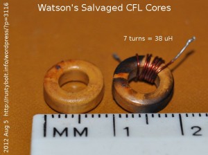
I found two CFLs (compact fluorescent lights) that were dead, so I opened them up to see what happened.  Both self destructed when the components burned up.  I decided that most of the parts were damaged by overheating and unsalvageable, so I took the toroids out and threw most of the rest away.  As can be seen in the picture, the core on the right was burned by the other overheated parts.  But not to worry; like the One Ring, these ferrites were forged in the hottest fire, and a little singeing of the paint doesn’t hurt the core at all.  Just remove the wire and clean it up, and then rewind it with some new wire.  Both cores were about 3/8 inch O.D. or about 9 mm, which is a very nice size for a Joule Thief.

As can be seen, the right core was wound with a winding of 7 turns, which I left on to measure the inductance.  The 7 turns measured 38 microhenrys, which is on the low side for a Joule Thief.  I will remove the (possibly overheated) wire and rewind the core with two windings of 12 or more turns, using 30 AWG or 0.25mm enameled wire.  This should give at least 100 microhenrys per winding, which is a good value to use for a JT.

default

2012-06-10 Peter’s Geiger Counter Questions

on June 10th, 2012 by - Comments Off on 2012-06-10 Peter’s Geiger Counter Questions

Peter emailed me with a question about Geiger Counters.  With his permission, I’ll quote his questions in the paragraph below and answer them following.

it´s Peter again – a few weeks ago I purchased a good, sensitive (and fully functional!!) Geigertube for measuring background radiation – the only problem is that it requires 1000 Volts. Of course I looked at Charles Wenzel´s page –> http://www.techlib.com/science/geiger.html
I built the supply with the single 10 mH choke first, cause I hoped being able to modify it appropriately, but I wasn´t able to get 1000 Volts out of it using 5 Volts 🙁 . There are other versions with a transformer capable of higher voltages using only about 3 or 5 Volts – I´d build them at once if I only knew what type of transformer he means and how to get it (or build it). Wenzel describes it as “a 1:1 600 ohm audio isolation transformer” or “phone xformer”. What is this? Can I build this myself? Have you got any tips for me?

As always I´d really appreciate your expert advice!

Wenzel’s Techlib has some very interesting projects, especially when it comes to radiation detectors.  I would trust his designs and I would not be afraid to build them, knowing that he has experimented with them and has a good grasp of their performance.  Having said that, I haven’t done any radiation detector projects and I do not know if his or others work.  I do know that from what I’ve read, the typical Geiger tube requires a very small current, microamps if I remember correctly.  So the power supply does not have to deliver much power.  The tube has a resistor in series, and this has a very high value, might be a megohm or so.

A quick and simple way to  build a high voltage power supply is to use the flash circuit from a disposable camera.  The large capacitor charges up to 300 volts or more, and the circuit draws a lot of current from the AA cell.  But by making some changes, the power can be reduced.  The circuit is similar to a Joule Thief, but with a high voltage winding.

I must put a warning here:  DANGER!  HIGH VOLTAGE! You can get a severe shock from this circuit.  Make sure you discharge the capacitor before you work on it.

 Instead of a rectifier and big capacitor, the output should be changed to use a smaller capacitor of a fraction of a microfarad, but the working voltage must be higher than 1000 volts.  The output should be a voltage doubler, which should give at least 600 volts.  The base bias resistor should be increased so that the circuit draws much less than the hundred or more milliamps it draws when it’s in the camera.  It should draw only as much as it needs to generate the current for  the tube, and that could be just a few tens of milliamps.  Also, 600 volts is not enough, so the battery supply is increased from 1.5 volts to 3 volts, and that should increase the output to the needed voltage.

I have very many of the 600 ohm 1:1 transformers used in phone equipment.  I have a blog that explains what it is

There is a Yahoo group called Geiger Counter Enthusiasts.  If you have a Yahoo account you can join this group and find out much more than I can tell you.  In order to see this link, you may need to be signed on to your Yahoo account.  In its first page it gives links to other Yahoo groups which may be more specialized.

Peter, I hope this helps you to solve your questions and get your project on the road.


default

2012-06-07 Harri’s LED Flashlights / Torches

Harri sent me some pictures of his LED flashlight or torch projects.  One uses a circuit similar to my Supercharged Joule Thief but without the resistor.  The other is a two transistor circuit.  With his permission I’ll quote his descriptions of the pictures.

Pic1:  This is like your SJT, only diode ditched and resistor value decreased to get maximum brightness. This circuit takes about 200 mA from a fresh battery and brightness is awesome. Conventional JT’s that I’ve made with 3k9 resistor takes about 40mA from fresh battery.

Pic2:  This one is without a handwound toroid and has 2 transistors. Works well.

Parts that I have used:

LED: 4-chip 80mA warm white diffused 10mm led from LED1.de.

Boxes: from dealextreme.com (around 1,5 $ a piece). SKU103845

for 2 AA-battery, SKU103862 for 2 AAA-battery. (Second battery contact removed and JT fitted in.)

Resistor for conventional JT: 2k7 or 3k9.

Toroids I use vary a lot, usually recycled from the dead energy saving lightbulbs. Some seems to work better than the others.

Pics 3, 4 and 5 shows complete units.

I haven’t tried replacing the diode with a short in my SJT. Without the extra DC bias caused by the diode, I would guess that there would be much less voltage across the capacitor and much less current through the transistor and the LED would be much dimmer using the same resistor (I used 1.5k in my SJT).  That’s apparently why his adjustable resistor gave the best brightness when set to 560 ohms.  My next thought is will the capacitor cause the same effect as in my SJT?  It increases the frequency and the efficiency a large amount.

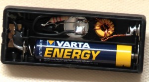
Harri sent me another two closeups, one of which I’ll show here, since it shows the parts and how they’re connected.  This makes it easy for the experimenter to use the same kind of case and get it up and running.

© RustyBolt.Info/wordpress
CyberChimps