default

2012-06-06 Joule Thief Brightness Controlled by Photocell

on June 6th, 2012 by - Comments Off on 2012-06-06 Joule Thief Brightness Controlled by Photocell

This Youtube video shows a guy’s Joule Thief that has its brightness controlled by a CdS photocell.  The ambient light changes the photocell’s resistance, which adjusts the JT’s brightness.  I haven’t yet seen the schematic but he promised another video with more will be posted soon.

I left a comment with a link to my blog that shows hot to use a LED as a sensor.  Someone mentioned that there was a device that used a microcontroller to drive an array of LEDs, and during the time the LEDs were off, the microcontroller changed to sensing the current from the LEDs caused by ambient light.  That’s pretty cool, because you could use them to make an interactive display that senses shadows from your hand, for instance, and changes the LEDs accordingly.

default

2012-06-05 4 White LEDs + 1 Yellow in Project Case – May 2003

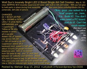
I built this in May, 2003 using an expensive plastic project case.  It worked very well, and put out a .lot of light thanks to the high performance transistors.  I added the yellow LED to make the light a little warmer, since white LEDs tend to have a lot of blue light. The URL I gave is still a good one.  His schematic shows a BAT48 Schottky diode and capacitor on the output.  I didn’t use these, the LEDs are directly connected to the collector of T2.

This photo was taken before I glued the components down to make it rugged enough to withstand rough handling.

default

2012-06-04 Watson’s Amplified Earphone

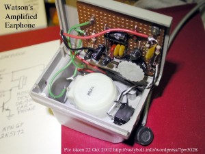
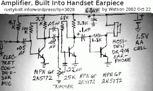
This picture was dated Oct 2002 so I had already built it and put it into service by then.  I took the handset of an old phone, and sawed off the handle and microphone, leaving just the part that holds the earphone.   I built the circuit on a piece of perfboard and installed it in the back cover of the earphone enclosure, and mounted the AA cell holder to the outside – you can see where the black battery wire goes through a hole and then back behind.  The electret microphone seen close and to the right plugged into the black jack next to it.   For the switch I just folded up a small square of paper and put it between the positive end of the battery and the holder.


default

2012-06-03 Watson’s Waterproof LED Flashlight

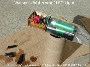
This pic is dated Nov 2003, which was about the time I built the light.  It was one of my early creations.  I built the circuit which used two transistors (not a true Joule Thief), a toroid, and three white LEDs. Most impottantly it used two AA cells in  series, which was kind of odd for the time.  The frame (I hesitate to call it an enclosure:-) was made from two short pieces of angle aluminum bolted to the bottom, a flat piece of aluminum.  The board and 2 AA cell holder were also bolted on.  It fit comfortably in the hand.

Since it was open frame, I decided I wanted to coat it wit a thick coating.  I bought a spray can of Grip & Guard, which is supposed to be used to put a thick coating on the handles of tools.  But the terms spray and thick coating are mutually exclusive: in order to get the can to spray, the fluid has to be thin.  I coated it with dozens of coats and you can see how thick it was in  the picture.  The only thing I really did was to get the switch gummed up so it was hard to turn on.  No, I really did not intend it to be waterproof.

The circuit lights the LEDs very brightly; in fact too brightly with fresh alkaline AA cells.  So I had to use depleted cells or else two Ni-MH rechargeable cells.  I still use it in some drawer somewhere.


default

2012-06-02 Microwave Oven Schematic

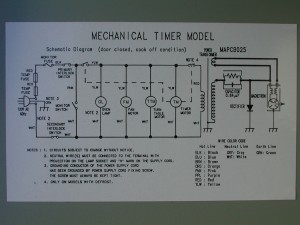
This is a schematic of the electrical system of a microwave oven that uses a mechanical timer.  It is so simple that hesitate to use the term electronic, because there are really only two components that are more than electrical: the magnetron and the high voltage rectifier diode.  The capacitor is a high voltage capacitor, and could be found in an electrical system.  Here it is used, along with the rectifier and magnetron, as a half wave voltage doubler, with the actual load being the magnetron, which acts as both a rectifier and load resistance.  The rest of the circuitry is simply electrical.  This makes it very easy to understand.

default

2012-06-01 Joule Thief Light from the mid 2000s

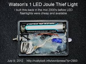
I built this light back in the early to mid 2000s when the LED flashlights were very expensive and generally not available.  As can be seen, it runs off a single AAA cell, and lights a single LED.  I used point to point wiring, then I put clear silicone seal over the circuit to hold it in place.  The white LEDs were expensoive back then; $4.00 at Radio Shack or $2.00 if bought online.  But the most expensive  part of the light was probably the box, which cost about $4.00.  The switch cost a few dollars, too.  Nowadays I have several Fenix LD01 single AAA cell keychain lights, and they perform so much better than this light that I can only say that it served its purpose back then, but has now become a relic.

default

2012-05-31 Joule Thief Powered By Solar Cell, Super Capacitors

on May 31st, 2012 by - Comments Off on 2012-05-31 Joule Thief Powered By Solar Cell, Super Capacitors

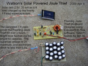
This is another of my pictures originally posted to my warsonseblog in 2009.  This uses a whole board full of 1F 2.5VDC super capacitors I got from an online surplus sales, I don’t remember which.  I think they were all used since the leads were short.  At that time I don’t believe that super caps bigger than 1 Farad were available, at least not for a reasonable price.

The Flashing JT uses a two transistor astable multivibrator circuit with assymetrical part values to make it stay off for much longer than half the time.  The third transistor is the driver, which switches only the base current to the final Joule Thief transistor.  This circuit uses more current than my Blue Blinky, but the flash is brighter due to the LED being on longer.

The solar cell is tiny and supplies only 20 mA on a really sunny day.  This disappears into the 20 farads like a cup of water into an empty swimming pool. It takes quite a while for the bank of super caps to charge up.


default

2012-05-30 Speaking of Fishing: Radioactive Tuna From Japan

on May 30th, 2012 by - Comments Off on 2012-05-30 Speaking of Fishing: Radioactive Tuna From Japan

Speaking of fishing…  Here’s a story that confirms what I discussed in my old blog shortly after the Fukushima Daiichi disaster.   From what I’ve read about the food chain, it leads me to still have concerns about radionuclides concentrating in the fish and other foods we eat.

http://news.yahoo.com/radioactive-bluefin-tuna-crossed-pacific-us-190121826.html

I was also reading the news online that the debris from the Japan Tsunami last year is now washing up on the shores of Oregon.

default

2012-05-29 Electrofishing

on May 29th, 2012 by - Comments Off on 2012-05-29 Electrofishing

Quantsuff sent me a link to a Youtube video about Electrofishing.  He said “Googling on Electrofishing yielded these numbers: 150-300V, 1-4A @ 16pps (15% duty).”  Looks like it might be fun to build one of those gadgets.

I got a Google Alert this morning about a Joule Thief, if you want to call it that, using a Radio Shack 120VAC to 12.6VCT secondary (as the primary), and he was driving it with a 2N3055.  He shows the waveforms on the ‘scope.  The frequency was down to 47Hz, so it seems like this should work even lower with a little adjustment.  It was putting out pulses at a couple hundred V P-P, and input current varied, but at 12V it was about a quarter of an amp.  The lamp lit up fairly bright.  The main point is that the transformer is available at Rat Shack for a reasonable price, and it seems to be capable of doing the job.  But just make sure you put a neon lamp across the 2N3055 to protect it against overvoltage, in case the output goes open (like when the probe’s out of the water).

I was thinking that the 555 timer chip could be used to gate the voltage booster at the 16 PPS rate, or two 555 chips (or one 556 chip) could be used to both gate the voltage booster, and drive the 2N3055 with the correct frequency pulses.

http://www.youtube.com/watch?v=RSVgXs7hxe8

default

2012-05-28 Alan Turing The Enigma

I’ve been reading this book on and off for the last week or so, a biography by Andrew Hodges of Alan Turing, who was the one responsible for the ideas of how a computer should be designed.  He wrote the thesis On Computable Numbers which explained the Turing Machine, the basis for the design of computers.  The book is not highly technical, but there is quite a bit of mathematics, logic, and philosophy in it.  The term Entscheidungsproblem is often used, a term with which I’m unfamiliar.

Later in the book Turing’s thesis Intelligent Machinery is discussed.  On page 384 the author stated

He showed that in a job taking more than 101017 steps, a physical storage medium would  be virtually certain to jump into the ‘wrong’ discrete state, because of the ever-present effects of random thermal noise.

I started to think about how incredibly large that number is (but that was not the largest number he used!).  Written on paper, that’s one with ten to the 17th zeroes after it! For example, let’s use 10101 steps as an example.  That’s 1010 steps, or one with ten zeroes after it, a very large number.

I got my scientific calculator out and started poking away at the keys.  I entered the 10 to the 17th into the calculator.  Then I reckoned that text would have about ten zeroes per inch in some fonts.  I divided it by ten and the number came down to 10 to the 16th power inches of zeroes.  Then I divided it by 12 inches per foot, and then by 5280 feet per mile.  The number was still huge.  I then thought, if I have a wheel with ten zeroes per inch around the circumference, and it was mounted on a handle, I could print zeroes on a very, very long paper strip.  I decided that I would print the zeroes at the speed of light, 186,000 miles a second(!).  I divided the number by 186,000, then by the number of seconds in a minute, and then by the number of minutes in an hour.  The number was now down to about 235, or in other words nearly ten days of printing zeroes at the speed of light, to get to the end of the paper.  Whoa!!

Thinking about it, any physically conceivable thing with that many discrete steps would have to have exceedingly minute steps, so these discrete steps would have to be easily disturbed by their environment.  For example, the number of particles in the universe is generally considered to be less than 10 to the power 100 (a googol), so this huge number of discrete steps far, far exceeds the number of particles in the universe.  If we used every particle in the whole universe to emulate this system of discrete steps, we would fall far short of the number needed, and I assume that it’s impossible to subdivide these particles any further.

In the last chapter of the book titled The Greenwood Tree the author gets into Turing’s essays on “How to build a brain”.  At the time when there were only one or a few working computers in the whole world, journalists were wildly speculating that a computer could think like a human.  Of course this was just their imagination gone wild, for today, sixty some years after the first computer, we still haven’t made a machine that comes close to human intelligence.

See my next blog for more mental flights of fancy.

© RustyBolt.Info/wordpress
CyberChimps