


 Watson’s Mattel Intellivision from the early 1980s.

2012-06-27 Photos of LED Lights I’ve Built (Cont’d)
(Cont’d from previous blog)
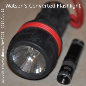
During the early days of my LED lights, I did some conversions of regular flashlights. The one in the picture is a Craftsman that used four AA cells and a regular incandescent flashlight bulb. I took the bulb out, broke the glass and removed it, and put three white LEDs, each with its own 33 ohm resistor in the lamp base. I made a dummy battery for the fourth AA cell. It worked reasonably well, but was somewhat bulkier than the Altoids tins – it wouldn’t fit in my pocket. The much smaller CMG Infinity light beside it was expensive, but served for several years as my keychain light. It was underpowered, with a single, not very bright LED. CMG held a U.S. patent on the circuit.


2012-06-26 Photos of LED Lights I’ve Built
Click more than once to enlarge
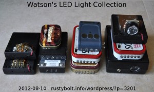
The LED lights I’ve built decided to have a get-together, so they met up in my kitchen. I think they may be up to some kind of conspiracy. I think they’re angry about not being used. When they were made at the beginning of the millennium, they were the only LED lights available. Well, we could buy a LED flashlight back then but they were fifty dollars or more. As time went on, they fell into disuse as the cheap, small LED lights became available on impulse item shelves of every grocery store checkout line. I’ve bought a few of those, but most of them got torn apart, as I scrounged the LEDs out of the light. I just can’t stand to waste two additional AAA cells when I can buy a ‘Miracle Beam’ single AA cell light for seven bucks that will save a lot in battery costs over its lifetime.
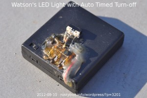 Looks like less than half of the LED lights I’ve built made it to the get-together; the others were exiled to far away and hidden places such as drawers, cabinets, shelves and other such places. Apparently they couldn’t be contacted about the get-together. One other one that came too late for the photo was a special LED light. As can be seen in its photo, there are three LEDs, three transistors a pushbutton switch and other parts imbedded in epoxy on the top of the case. This timer circuit shuts off the LEDs a minute and a half after the pushbutton is pressed. It makes it very difficult to leave the light on and run down the batteries.
As for the other pictures, I guess I’ll have to say a few words about those conspirators.
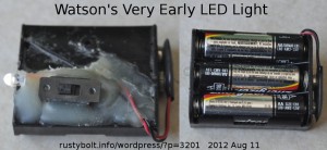 Earliest – Probably my earliest attempt – about 2000 or 2001 – at building a light that I could actually carry around. I just hot glued the LED, resistor and switch to the surface of a 3 AA cell holder (see the photo). I had to put a heavy rubber band around the middle to keep the middle AA cell from falling out. I had already breadboarded a V boost circuit using a LED, single AA cell, toroid, transistor and resistor, which later became known as a “Joule Thief”. I had problems getting the LED to light brightly; the coil had too many turns of too thin wire, and the transistor was not capable of handling enough current. My experiments with this became much higher priority when pirate speculators the likes of Enron gouged the California electricity suppliers and they in turn declared that there would be electricity shortages and possibly rolling blackouts (more on this here). I was very concerned that the incandescent lamp in the Mini Maglites I carried around might give out when I was stuck in an elevator or basement.
Early on, I bought the white LEDs and enclosed battery holders from Radio Shack (the two on the left of the picture) and I just glued the LEDS and resistors to the top. The holder had four batteries but I needed only 3, so I had to fill one of the battery slots with a dummy battery, which consisted of a 2 inch long screw with a washer at each end, and nuts to hold them on. This provided a short between the ends and was held in by the spring in the holder. The holder had a built-in switch so no need for an external one. The white LEDs from Radio Shack had too wide of a beam, so they weren’t very bright and three of them were not really enough; that was why I added the fourth LED to one of the holders.
Not long thereafter, I started building the lights in Altoids tins (bottom two of the third pile from the left, and the middle of the fourth pile from the left). They were a convenient size and other people donated the empty tins to me. They work well for other projects, too. I takes a bit of time to drill and file out the hole for the switch, and the thin metal is easy to bend so any work I did was a bit of a problem. But they are free; the project boxes were much more expensive – from $4 to more than ten dollars U.S. depending on the size.
I found the smaller Velamints tins at the store (top of the second pile from the left) and I bought several. I could squeeze a single AA cell holder, three LEDs, a small circuit board and a submini switch into it. The circuit board held a two transistor voltage booster circuit with a high current coil driver transistor, so all three LEDs were lit very brightly.
Cont’d in next blog.
Back to theorizing about conspiracies…
2012-06-25 Watson’s 3 Transistor Earphone Amplifier
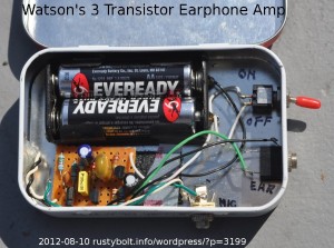 This amplifier has been around for awhile, however the date code on the Altoids tin is “Use by 22 Aug 06”, so it had to be made sometime not long before that date or later, most likely later. I used a high gain, low noise Japanese transistor (looks like a 2SD636) for the preamplifier, and two 2N3904 transistors. The Altoids tin was a convenient size to hold everything, as can be seen in the pic.
Originally the miniature electret condenser microphone on the left side of the tin was directly connected to the input. Later I added the microphone jack.
2012-06-24 FET Dip Meter
Cyrodyl posted a schematic file named FET Dip Meter.PNG (you may have to be logged on and joined to the group to view this), and this is my comment about it. I posted this comment file to the Yahoo group RegenRX2, which is the overflow from the RegenRX group, which deals with regenerative receivers.
Comments on FET Dip Meter.PNG (I own and use a Heathkit FET Dip Meter)
The M1 analog or “wiggle stick” meter is a 50 uA meter movement, with an
internal resistance that is not given. R9 is a 1.2k resistor in parallel with
M1. Assume that the M1 internal resistance is 1.2k, then the meter and R9
require 100 uA for full scale deflection because half of the current will be
shunted through R9.
A few of the requirements for this meter are that it be small, so that the Dip
Meter can be hand held and used in places such as wherever a coil might be
located. The meter does not have to be accurate, because it is only indicating
the relative strength of oscillation, not the absolute value. Thus the numbers
on its scale are relatively meaningless. It does have to indicate small
changes in strength, such as when a low Q tank circuit is being dipped.
Most meters cannot meet these needs. It is uncommon to find a small analog
meter because the meter scale is too small to read accurately. The Heathkit
uses a small edge mounted meter, which are even less common today because
analog meters have been mostly replaced by digital meters.
This seems to indicate that a few LEDs could be used in place of the meter. I
think 1 or 2 LEDs would not give enough range and still be able to indicate
small changes. 3 LEDs or more might be suitable, with the proper circuit. The
LEDs would use more current, but this is not a problem because the Dip Meter is
used only a few minutes a month or even less and the battery should last a long
time. It would need 1 or 2 transistors to boost the 50 to 100 uA up to enough
current to drive the LEDs.
Another option is to use a digital meter. The 50m uA passing through the 1.2k
resistor causes 60 millivolts drop across the resistor. The cheap DMM on the
200 millivolt range could indicate 0 to 60 millivolts. I’m unsure if it would
be good at indicating the small changes that the analog meter can show. It
would be interesting to try it and see.
Lately I haven’t had any time to do experimenting.
2012-06-23 FM Wireless Mic With Timer
I wanted to listen to the morning news while I was preparing for work or whatever in the morning, but I didn’t need the full TV set in the bathroom. All I wanted was to hear the audio so I could catch the weather and a few newsworthy items. So I built a FM transmitter with an RCA plug input so I could plug it into the audio output of my VCR. It was only one or two transistors and a 9V power supply with a wall wart AC adapter.
I used a cheap pocket FM radio in the bathroom, and tuned it in to 90.3 MHz, about the only place on the dial that was not occupied by a FM station. I had it running 24/7 for more than a year, when some neighbor said that someone was looking for me about fixing my cable TV. I told the neighbor that I didn’t have cable TV and ignored it for awhile. Then some engineer for Sprint left a note on my door asking about fixing my cable TV, and left his phone number. I called and talked to him, and told him that I didn’t have cable TV. He said he had traced a radio signal down to my home, and it was interfering with the cellular phones in the 900 MHz band. That really puzzled me because my little FM transmitter was set to 90.3 MHz. Apparently the 9th harmonic of my signal was strong enough to cause interference at that frequency – the cell tower was only a few hundred feet away, close enough to pick it up. So I told him that I would take care of it.
What I did was disconnect the FM transmitter, and I never used it again. Instead I ran a phone wire with two pairs 50 or so feet around the baseboard, and connected it to the TV and a speaker in the bathroom. I could turn it on whenever i was in the bathroom, and the cheap little speaker was good enough to hear what the latest news was. It was completely private – no one else could hear it – and it couldn’t interfere with anything.
‘In my new place, I wanted to do the same thing again. I thought about running wires, but now that I’m not so close to the cellular tower, I decided that I should be able to use a FM wireless microphone. I put a wireless mic that I made next to the TV, put two AA cells in it, and turned it on. I used a cheapFM pocket radio in the bathroom and it worked great. My only problem is that I forgot to turn it off, and it stayed on for hours transmitting the TV. When the TV was off, it was picking up any sound in my living room near the TV. All this time it was running off the two AA cells, which were being wasted while transmitting nothing when things were quiet.
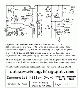 I thought about a solution and considered using the same circuit that I used for my Commercial Killer Junior, three transistors with a multi megohm resistor discharging a 22 uF electrolytic capacitor, and the microamps of current then was amplified to turn on the transmitter. It worked for a few minutes to keep the transmitter on long enough to kill the commercial (see the schematic). But now I need a time interval of much more than a few minutes; probably about thirty minutes minimum. The timing capacitor is going to have to be more than ten times as large, maybe 470 uF. I think the resistors I used were 2.2 Megohms. Now I may have to use even higher values. That means less current for the transistor. I’m thinking that I may be able to use a CMOS FET instead of a transistor so that the base or gate current can be zero.
The CK Jr. doesn’t turn abruptly off; the supply current tapers off until the voltage is nearly zero. This isn’t a problem because the transmitter quits working long before it gets near zero. The one symptom of this is that the transmitter frequency is somewhat voltage sensitive, so it gradually goes off channel. This doesn’t hurt the CK Jr. because you want it to stop blocking the program after the commercial. But it might be a problem with listening to the FM radio.
I built one of these circuits with another transistor, which was used to speed up the turn off as the capacitor reached the end of its discharge.
Other Ideas
I had another idea. I could rectify the audio after it has been amplified, and use it to turn on the transmitter. When there is no audio, the transmitter would turn itself off. This works best if I plug the transmitter directly into the TV. I don’t want the transmitter turning itself on when there is a loud noise near the TV and a microphone picks it up. I might need an override switch so that the transmitter can be turned off at most other times so it will conserve the batteries.
Back to experimenting…
2012-06-22 Delta AFC0912DE Fan
The fan is labeled:
DC BRUSHLESS
Model AFC0912DE
Dell P/N P2780
DC12V 2.50A
Delta Electronics, Inc.
I work with Dell PCs and I had a CPU fan laying around that came out of an older Optiplex PC. I had connected it up to a 12V power supply much earlier, and it acted very odd.
FIrst off, older fans had two wires: a red positive 12V and a black ground. Later, fans came with three wires: red for +12V, black for ground and a white or yellow wire for the tachometer to tell the MoBo that the fan was spinning, But this fan was different. Instead of three, it had four wires: red, black, white and blue. So I connected the 12V up to the red and black wires. It would start out slow, and gradually speed up to a high speed, then, Kerchunk! It would abruptly come to a near halt. then it would repeat the process. It was either putting out almost no air, or whining at high speed and drawing over 2 amps from the power supply. I kind of gave up and tossed it in the spare parts bin, where it sat for a long time.
I finally got around to try to get it to work. I went by the old maxim “An hour in the library is worth ten in the lab.” I went online and searched for information about the fan. I came across others who were trying to get another fan to replace their noisy Dell fan. Finally I found out that the red and black wires were the positive 12V and negative, and the white and blue wires were the tach and PWM speed control wires. But I did not find any information about what the PWM control was or how it worked.
So I started experimenting with the PWM control line. I tried a few different value resistors from +12V to the blue wire, and from negative to the blue wire. I found that if I put a 1k resistor from the blue wire to negative, the fan stopped acting weird and would run at a constant speed, not very fast but at least it was steady and quiet. Now I can connect the fan to a 12V wall wart, and plug it in, and set it on its edge on the table without having to worry that it was going to jump off and fall on the floor due to its kerchunking behavior.
Back to experimenting…
2012-06-21 Old Photo of Neighbor’s Ham Shack
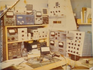 As I’ve been moving, I have uncovered stuff that I have long forgotten and didn’t realize I had. Here is an old stained and cracked Polaroid photo of a neighbor’s ham shack and test bench. I’ll have to see if I can contact him and let him know that this photograph is still around.
2012-06-20 Homebrew NMOS Transistor – Really!
I wouldn’t attempt this in anything less than a clean room. But she does it in the kitchen, apparently. You can click on the link and see it in action. It actually works.
2012-06-19 Joule Thief Odd Behavior
I left a few comments on this Youtube Video of a Joule Thief that behaves oddly. The waveform on his o’scope is the usual JT waveform, but it ‘gallops’ – the tops of the waveform have a periodic change up and down, which seems to change with the scope timebase setting. He gives a schematic later in the comments. Essentially it’s just a simple conventional Joule Thief with the 1k resistor replaced with a 50k potentiometer. He calls them harmonics, but I would call them subharmonics because harmonics are multiples of the fundamental frequency, but these are lower than the fundamental frequency.
He investigates this further with a followup video where most of the clip leads have been removed, leaving the circuit much more visible and uncluttered. The elimination of the clip leads means less stray capacitance which might be affecting the circuit. As can be seen, the circuit is simply a Joule Thief.
Now that I see what the circuit looks like, I can replicate the circuit exactly as shown. I’m using a DSO-2250 digital sampling oscilloscope with the software running under XP. I connect the scope probe to the collector and the scope ground to negative. The waveform I see does not have any of the galloping or subharmonics that his circuit has. I have scoped dozens of JT circuits with my scope and also with an analog o’scope, and they just don’t have any of this odd behavior.
He says that he has changed coils and transistors and the odd behavior remains. I don’t remember if he said he had changed the LED. The only other parts are the battery and pot, and they are so simple they should not be contributing to the odd behavior.
My only conclusion is that the mini digital sampling oscilloscope he is using must be causing the odd behavior. I am guessing that as it is sampling it is internally generating enough of a signal that the signal is beating with the JT input, which mixes and causes the subharmonic. I don’t think that the power line could be causing it, because the JT circuit and scope are not connected to the power line – both are battery operated. To verify this, it would be easy to put the JT and scope on a tray and take them outside and away from any power lines such as the inside wiring of a dwelling.
Back to pondering…
