


At Xmas, I had more than a dozen of the Blue Blinkies under the eaves. Last year a guy at work gave me a bag full of used AA cells, more than 5 pounds, must’ve been well over a hundred. Some measured 1.3V, some measured less than a volt, and some leaked juice and I had to dispose of them. Using magnets, I stuck a dozen of the working AA cells on to JTs that use germanium transistors, so they’ll work at less than a half volt. They just sit there and glow, and when they wear down, usually on the weekends, I take off the really dead AAs and put on some more cells. So far I’ve got about half of them finally used up, as in really dead, and I’ll probably get done in another month or so. I could put them on the Blue Blinkies, but when I built the first Blue Blinky, I put it on a partly used AA cell, and it was dim but still blinking 21 months later. I figure that even if I put a dozen AA cells simultaneously on the Blue Blinkies, it’ll take me more than a dozen years to use up all those AA cells. So let’s get it over with somewhat quicker and just drain them dry with the germanium Joule Thiefs.

2013-01-21 Lighting An LED With a Candle
This experimenter’s circuit uses ten BF245 JFETs in parallel to get the 30 to 40 millivolts up to LED voltage. Here’s the Youtube video. IT looks like I will have to reduce my primary winding from two turns to one turn.


2013-01-20 Very Low Voltage Joule Thief Ver. 2
I removed the two core coil from the circuit of my previous blog and put the 550 turn coil in its place. In my haste to see how well it worked, I connected the power supply clip leads backwards, so positive was connected to negative, etc. But I really didn’t notice, because it was working. But then as I was working on it, I realized the mistake, and corrected it. But now it wasn’t working. Okay, so it worked with the power backwards but not with it correctly connected. Then I remembered that JFETs can be symmetrical: the source and drain can be interchanged. This must be what’s happening when I connected it backwards. So what I needed to do was reverse one winding to get it to work.
I unsoldered the fine wires of the feedback winding, and reconnected them the correct way. I turned the power on and it started working. But the LED started to glow at 87 millivolts, which was 6 or 7 higher than the original coil. And the oscillations showed up on the scope at 48 millivolts, about ten mV higher than the original. These are still quite low, but I was disappointed that they were not as good as the original. After all, I spent an hour or two winding all that wire onto the core – and got no benefit for it.
See the original blog here.
More on Low V JTs here in Ch. 3.
Back to experimenting…
2013-01-19 Very Low Voltage Joule Thief J105
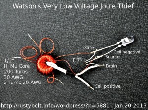 I wound a half inch core with 200 turns of 30 AWG enameled wire and connected it up to a J105 JFET. The JFET doesn’t require a resistor, so there’s no power wasted there. I used two turns of 20 AWG stranded insulated wire for the primary (drain) winding, so the ratio is 2 to 200 or 1:100. I just about filled up the core, not much room left for any more turns. The LED was an aqua or blue-green that needs about 2.8 volts for full current of 20 mA. The core was out of a network board of a PBX. It’s high permeability. The curlycues are the splices at 50, 100 and 150 turns. The winding was tedious, and took awhile – that’s why I broke the windings up into smaller 50 turn pieces. The JFET was connected with the LED across the source and gate, with the cathode to the gate so it lights when the gate goes negative.
Note: Connecting the LED to the source and drain – like a normal JT – would not light the LED. Since the turns ratio is 1:100, if the peak voltage across the primary winding could rise to 3 volts to light the LED, the peak voltage across the feedback winding would then be 300 volts, and that would seriously damage the JFET.
Results
I used a power supply with a ten turn pot so it could easily go down to below a quarter of a volt. In the first iteration I had 150 turns and it just barely glowed at 160 millivolts supply V. I decided to wind another fifty turns on to go down even further. With 200 turns, the LED barely glowed at 125 millivolts, however the scope showed it was still oscillating well below that, clear down to 60 millivolts. The JFET just doesn’t develop enough voltage to light the LED. The frequency was highly dependent on the supply voltage, but at one point it was about 8500 Hz.
Conclusion
I feel confident that if the wire was smaller or the core was larger and I could get more turns on the core, the JFET would be able to drive the LED at even lower voltage. I think I’ll try for a larger core because the 30 AWG wire is about as fine as I want to work with. Even then it tended to kink and tangle. Besides, if I use a larger core I can wind some of the wire onto a bobbin that will pass through the core and I won’t have to have any splices. The only problem is that the thinner wire has higher resistance and since the load is driven by the current from the thinner wire, the current will be lower than if it were heavier wire (the LED doesn’t get much brighter above a quarter volt). But in order to get a higher turns ratio, the core is going to need more than two hundred turns; probably three or four hundred.
This is the first time I’ve done any real experimentation with the J105. What I had in mind this time was to get down to 40 millivolts so I could connect it to a thermocouple that I discussed earlier. But right now, I could get a decent glow by connecting four or five thermocouples in series for 160 millivolts. I’ve had the J105s for awhile but I really didn’t do much before, mainly because I knew I had to wind a lot of turns and it’s tedious, time consuming and BORING. But now that I got it to go down to 1/8 volt, I may take some more time and do another coil. However my earlier blog was doing about the same with the TN0702 and a button cell. And the LED just didn’t barely glow; it was drawing 45 mA and the LED was a lot brighter.
Update Jan 20
Everything stayed the same except I added two things (see the picture). I added a 2200uF bypass capacitor across the supply lines. I wound another coil with 200 turns of the same 30 AWG wire. Again I wound it in four sections and connected all sections in series. I then coupled it to the original core with a heavy wire link. I got the phasing right the first time; I tried it the other way and got no light at all.
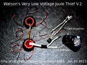 Results – I guess the words would be less than I had expected. When I powered it up, the LED again lit at about 125 millivolts. No change from the original circuit. However, when I looked at it with the scope, the circuit started to oscillate at 31 millivolts, about half of the original circuit. That would make sense because I have effectively added twice the number of turns to the feedback winding so it should be able to oscillate at the lower voltage. I’m pleased to see that it will work at such a low voltage, but disappointed that the LED did not light at a lower voltage. I have no explanation, but it might be that below 1/4 volt, the different metals coming in contact with each other, such as solder and copper, cause different voltages that tend to disturb the circuit. Another possibility is that the J105 just can’t put out enough current at that low voltage to light the LED. I want to try winding another larger core with more turns, maybe with finer wire to see if it will do any better. Right now, it’s doing much better than I had done before, so I can’t say that I haven’t made progress.
Update Jan 21
My speculation was right. I tried adding a second J105 in parallel with the original, and the LED lit at below 100 mV. Wow! So I soldered together two J105s in parallel and added them to the original and things looked even better. Double Wow! I got the LED to light at 80.5 millivolts, and the scope showed it started oscillating at 35 millivolts. That’s getting even better! The frequency was 5.8 kHz. If I had more JFETs I might be able to go even closer to the 40 millivolts I’m trying to achieve.
I was using clip leads – short ones, only4 inches long. By removing them and soldering the JFETs directly to the original, I subtracted about 5 millivolts from the LED’s turn on point, about 75 millivolts. I then scrounged up a fourth JFET and added it to the other three. Now the LED’s turn on point is about 78 millivolts, and the start of oscillation is 31 millivolts. But my scope and meters may be affecting the measurements. The supply current was about 100 milliamps.
A Summary of the Circuit at this point
Two coils link coupled, primary two turns 20 AWG, feedback winding totals 400 turns of 30 AWG wire. Four J105 JFETs in parallel. The aqua (blue-green) LED is connected between the gates and sources, with the cathode toward the gate. No resistor is used. Supply voltage is less than 1/8 volt.
Because the JFETs oscillate at much less than the LED light, I believe that the LED can be lit at a point nearly as low as the oscillation if the current through the JFETs is increased. I think that if enough JFETs or higher current FETs are added, the LEDs will light up somewhere near 35 millivolts. It’s a matter of finding a way to get the added current. I may try other types of FETs to get the higher current.
I have finished winding another larger coil, with 550 turns of wire. I will add another blog on this second version.
Back to experimenting…
2013-01-18 Watson’s “Wireless” Joule Thief
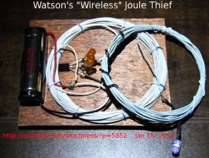 I was watching Sohei’s “wireless” light on Youtube and I decided to build a similar one. It’s not much different from the Tesla pancake coils I was experimenting with recently. This “wireless” Joule Thief is not really wireless, because it doesn’t really radiate radio frequency energy. It’s just a transformer with the secondary winding separate and independent from the primary winding, with the energy coupled electromagnetically.
To make the coil, I used a hank of white wire from a ten foot parallel printer cable, and a shorter hank of wire from a six foot cable. They are both 26 AWG, and the longer one is the primary (collector) winding and is about 23 uH and 0.232 ohm DC resistance. The shorter one is the feedback (base) winding and is about 13 uH. They’re just put together and tied down to the piece of plywood with some short lengths of wire. The inside diameter is 2.8 inches or 70mm. The secondary (LED) winding is about 22 uH but it looks thinner, maybe 28 AWG white wire and is 0.345 ohm DC resistance. The LED is just soldered to its ends. The other parts are soldered to the heads of small screws that I put into the plywood at various locations.
The transistor is a 2SC2500D, which is really hard on the AA cell. The resistor is the standard 1k, 5%, 1/4 watt resistor. The two amber LEDs are in series and are connected between emitter and base with the cathodes toward the base. They prevent the base voltage from going more negative than 6 volts, and you can see they are glowing slightly, showing that the base voltage is going down to negative 6 volts.
The circuit draws 400 mA from the 1.5v supply, and the AA cell doesn’t last very long. The 2SC2500D is a very high gain power hungry transistor and sucks a lot of current. I could reduce it by increasing the value of the resistor. The white LED is not lit very bright because the secondary coil is not centered over the primary. When I put it directly over the primary the LED gets much brighter. But the LED is polarity sensitive: if I flip the coil over, the LED is much dimmer. I think this coil needs some more turns; the LED is not as bright as it could be, considering all the current that the circuit is drawing from the AA cell. I’m going to experiment with this coil some more. I have also placed the chokes from the pancake coil inside of this coil and the LEDs light up.
Update Jan 19 – I changed the secondary to a coil having a much longer wire, It measured 0.625 ohm and 56 uH. The LED lights up much brighter, and is beginning to act like a flashlight or light, as Sohei showed in his video.
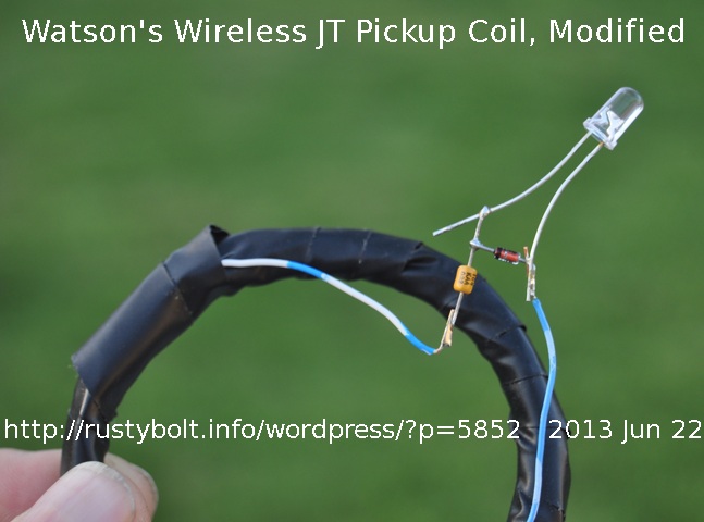 Update Jun 22, 2013 – I added a half wave voltage doubler to the picjup coil between one of the coil wires and the anode of the LED. But the LED serves as the second diode, and there is no filter capacitor. This arrangement reduces the loss and helps the LED when the pulses are negative going, since it captures the negative going pulses. I used a 0.1 uF capacitor between the coil wire and the diode, which was a 1N4148.
2013-01-17 Questions About Joule Thief Transistors
This is a continuation of my earlier Questions about Joule Thief.. blog. Paul, who is from the U.K., said he is using the BCY51, BFY51 and 2N1711 transistors, and wanted to know if I thought they were suitable for a Joule Thief.
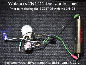 The information I could get online about the BCY51 was scanty, but what little I saw seemed to indicate that it was made for high radio frequency use and cannot handle the JT current of over 100mA, therefore I would say that it is not suitable for a Joule Thief, however poorly it may seem to work. According to the datasheet, the BFY51 is a general purpose transistor that can handle a full amp. The Philips datasheet did not show any graphs. The hFE at 10V and 150 mA is given as 40 minimum. That’s much lower than the typical 150 or so current gain of a PN2222A or 2N4401. The Vce(sat) at Ib=15 mA, Ic=150 mA is 0.350 V maximum. That is higher (not as good as) the PN2222A, which is 0.3VDC. Because it can handle the current but has the lower gain and higher Vce(sat), I would put this on the lower end of suitability for a JT. It is going to need a lower resistance than the 1000 ohms of the typical JT.
The Last transistor Paul used was the 2N1711, and I have a few of those. According to the ST datasheet, the 2N1711’s Vce(sat) at Ic=150mA, Ic=15mA is typically 0.5 V, maximum 1.5V. Oof! That last figure is the same as the supply voltage!! The JT transistor must conduct well over 100 mA in order to charge up the coil during its on time. Even if the 2N1711 is at the typical 0.5V, one third of the supply voltage will be wasted across the transistor as heat. I took one 2N1711 and soldered it into a Joule Thief which already had a BC337-25 in it. The BC337-25 was drawing 88 ma from the 1.5V supply, which is what I would expect from a Joule Thief putting out nearly 20 mA to the LED. When I put the 2N1711 into this circuit, the supply current dropped down to 64 mA. To get the supply current up to 86 mA, I had to drop the resistor from 1k down to 470 ohms. The lower current gain of the 2N1711 is what made the difference. I don’t have a current sensing resistor in series with the LED, but from the many other JTs that I’ve experimented with, I already can predict that the LED current will be only a dozen or so milliamps instead of the 18 to 20 it was getting from the BC337.
To me the choice is obvious. The 2N1711 and other transistors he has experimented with are packaged in a metal can, which costs many times as much as a BC337-25 in a plastic package. The metal package is not needed; the heat dissipated by the transistor (when it’s the proper transistor with a low Vce(sat)) is minimal and it won’t get warm. And the BC337-25 makes a very good choice for a JT transistor. The BC337-25 is available from Farnell for the miserly sum of 2.50 to 3 Pounds for 100. The 2N1711 will cost you 40 Pounds for a hundred. Ouch!
If you want to see an excellent JT transistor, try the ZTX1048A, from Zetex in the U.K. The gain at a half amp is typically 450, and the Vce(sat) is an incredibly low 0.027 volt! These are more expensive, but can drive several LEDs. Here’s a link to the Farnell catalog.
I used a lot of PN2222A transistors in my Blue Blinkies for Xmas decorations; they’re good for experimenting and available at Radio Shack stores. I noticed that they don’t seem to be in Farnell’s catalog. The 2N4401 is another one available at Radio Shack stores. The BC337-25 and BC337-40 are great for JTs – probably the best buy for the money at 5 cents apiece. The -40 will act like a racehorse in a JT and you have to say “Whoa, Nellie!” by increasing the resistance to 3.3k or more, lest the LED get too bright and burn out. The complimentary (opposite polarity PNP) to it is the BC327-25. The overseas company futurlec.com has components in small quantities and the shipment I got a few weeks ago took a couple weeks to arrive, but then some delay might have been because of the Xmas holidays. However I did have a problem (see my other blog), and they finally rectified it by sending me replacements which arrived a few days ago.
Paul asked about
The transistors that Paul said he has, for their day, were very good. But they were the ‘jack of all trades’ type which didn’t have any outstanding attributes. They were designed with few compromises. The transistors of today, such as the ZTX1048A, are more specialized, and have a few outstanding attributes, such as the Vce(sat), and high gain. But in order to get those, they had to sacrifice some other place. One sacrifice is the ZTX can only handle 17.5v maximum, less than half of what those earlier transistors’ maximum. There are other sacrifices, too. The laws of physics can’t be ignored, and the transistors have to obey just like everything else. One thing that has improved is the manufacturing process, so that newer transistors don’t have to have the greater margins of safety that older ones had. For instance, the equipment lets the designers control the process to closer tolerances, which allows them to make the transistors so that the junctions are closer together, thus giving higher gain. And the same applies to the chemistry and temperatures. One thing that bothers me, though, is that Fairchild or Philips may sell a transistor to us for five cents and still make money, but the ZTXs sell for nearly twenty times that much, yet they’re all made from the same silicon and similar processes. I guess it’s a question of supply and demand.
One important point. You don’t need a ZTX1048A for a Joule Thief with a single LED. This transistor is so powerful that you want to use it for a large number of regular 5mm LEDs or for a 1 to 3 watt LED. I tell others to use the BC337-25 because it matches up well with a single 5mm LED. If you use its higher gain version, the BC337-40, you will get more than the required 20 mA for full brightness with 1 LED; instead you can use it to power two or three 5mm LEDs. The ZTX can power many more than that, so don’t buy them if all you want is to power 1 or 2 LEDs.
You don’t need to order a minimum at some stores. I got some of my transistors from eBay in smaller quantities. But I have also had some bad experiences with eBay sellers. Almost all of the commodity priced components there are new and may even come on tape, so you know they’re not used. But some vendors sell certain things, especially LEDs, at good prices, and they don’t tell you (or may not know themselves) that these are factory rejects with flaws such as LEDs with air bubbles in them. For experimenting, this isn’t so much of a problem, but if you’re building something like a flashlight, you want a tight beam of light, not something that’s diffused by air bubbles.
2013-01-16 LED Light Bulb – More Discussion (contd)
Dilemma Changing Incandescents To CFL or LED
Both CFLs and LED lights can be damaged by excessive heat, which often happens and makes people wary of buying them because they often think they have purchased “Duds”. The problem is that since incandescents lived on heat, the fixtures either ignored the heat or tried to keep it in for fire/safety reasons. Now that the bulbs are temperature sensitive, people have to use their good judgment and keep the CFL and LED light from overheating. I used socket extensions on my recessed fixtures, so more of the LED light is exposed and stays cooler. Some fixtures turn the fluo tube sideways so that less of the tube is exposed to high heat. But people are not wanting to spend a lot of money to remodel their light fixtures so that the CFLs or LED lights are cool. I see the recessed LED light fixtures selling for fifty dollars or more at the big box stores, and that doesn’t include the cost of installing them if you use a licensed electrician.
One important point about the Philips L Prize light: it uses a white light emitting phosphor that is outside of the LEDs, so the heat and light have much less detrimental effect on the phosphor. Moving the phosphor to the plastic covers was an excellent way to solve the White LED’s typically short lifetime. BTW, years ago I saw in an electronics catalog LED “boots” that fit over a blue LED and emitted white light. So this phosphor is not a new technology, it’s probably many decades old. Remember that the black and white TVs used white light emitting phosphor that was developed from the phosphors used in radar sets during WW 2.
I’m hoping for more motion sensing and/or proximity detection so that the LED light will turn on only when you are present, then off quickly. This will take care of a lot of the savings in power. However the sensor(s) must not use very much power themselves or else they will waste more power than they save. One way to do this is to shut off the sensor circuits most of the time and only turn them on for a fraction of a second every second or three. Also turn the light circuitry off during the daytime, so it has to be activated manually.
Task lights are a good way to save power yet get a bright light. A task light brings the light source closer to the reading or work areas where the light is closer and more concentrated. The closeness reduces the need for a powerful light source, thus saving energy. Task lights can be purchased for a minimal amount. A task light can consist of a socket with a reflector, a gooseneck or flexible arm, and a base, which might be a heavy weight or a spring clamp to clamp on to the edge of a desk.
Here are some images of task lamps from a Google search.
Here is some good information and pictures about task lighting and glare.
Last weekend I made a LED task light using a Cree emitter running at 0.6 amps. Since it’s on a gooseneck near my reading and work, the light is much brighter and it only uses about 3 watts.
2013-01-15 Developing a LED Light Bulb – High Output And Efficiency
Quantsuff sent me a link to some Kickstart entrepreneurs who are developing a high efficiency, high output LED light bulb. The lights are equivalent to 75 and 100 watt incandescent lights. They have already surpassed their $20,000 goal, so they really don’t need more contributions. One big reason why I would not consider contributing is that they have chosen a very bad product with which to try to compete in a market that is full of commodity priced light bulbs, and full of uninformed consumers who would never consider choosing a light bulb that costs tens of dollars when they can buy the same light bulb for under five dollars, sometimes for only a dollar or two. Those consumers have no concept of investing in technology to save money in the future.
Another reason why I would not consider backing them is the Philips L Prize LED light bulb. This is made or assembled in America, it is high light output, low power consumption, well designed and high quality, and it is marketed by one of the biggest companies in the world. I don’t believe they have a snowball’s chance in hell of competing against Philips. Or against GE or other major light makers, for that matter.
I have been praising the merits of the L Prize light to some co-workers who are techno-savvy, and it has fallen on deaf ears. Most of them have decided that the CFLs are good enough and save them enough money to not even consider changing to LED lights. I’m of the opinion that these entrepreneurs will never be able to market their product effectively to maintain a high enough sales to be able to get their costs down to a profitable level.
There is another factor that has taken place. Philips has made a change to the L Prize light that will guarantee that the lights will last a long time. They moved the white light phosphor from inside of the LED to outside, where it cannot deteriorate so badly. The biggest problem with white LEDs is that they may operate for only a few hundred hours, and the light output drops so drastically that they are no longer able to do the job. The ones I’ve tested have dropped to less than 1/4 of their original light output, probably more like 5 or 10 percent. They are useless for illumination. I think that these entrepreneurs may face this same problem when they have put a few hundred hours on their lights.
I could go on and discuss some other factors that are not in their favor, some of which they talk about in their prospectus, The challenges are formidable; there are so many external factors these entrepreneurs face that it is doubtful they will be able to succeed. Even so, I wish them the best of success, for the world needs more LED light bulbs.
2013-01-14 Questions About The Joule Thief, Particularly The Coil
I received an email from Paul, with some good questions about the Joule Thief, particularly about the coil. He’s given me permission to use them in this blog. Here is his intro and first question:
Imagine 1st an average JT circuit just as frequently made. 1 transistor, 1 white LED, 1 resistor, 1 battery at say a steady 1.3v, 1 toroid. Assuming common components used where not specified. Standard circuit. E.g.
I have not got the test gear to answer these questions definitively myself. I wonder what happens if you make some single parameter changes seeking an ‘optimum’ …
1) Keeping the length of the bifilar winding wire the same (to keep the same resistance you see), but increase or decrease the inductance by changing number of turns actually used on the toroid. The frequency rises with fewer turns, but what about the input current and efficiency? If you wished a high output to give bright LEDs which way would you go? Where is optimum?
I go into detail about this in my earlier blog. Remember that you are not limited to using a toroid. You can use an air core too, or other shaped cores. I would start with the most turns I could easily wind onto the core, but I would not use very thin wire. Then after getting it running, I would unwind a few turns at a time and measure the LED current as I discuss below. If there are a few inches of wire left unwound, then it will be easy to wind that wire back onto the core if I feel I unwound too many turns.
2nd Q.
2) Is there any advantage to a different ratio of turns on the toroid rather than 1:1?
Using the 1:1 ratio makes it simple for the experimenter and also makes it easy to wind both windings at the same time – bifilar wound. But the windings can and should be wound with different ratios depending on other factors. For instance, if you wind many more turns on the feedback winding, the JT will have more sensitivity at low voltages and will run with a battery that has less than a half volt. Also, if you have a 1:1 ratio, and there are two or more LEDs in series across the output, then the voltage across them will be 6.6 or more volts. The transistor’s maximum emitter to base reverse voltage is 5 or 6 volts, and the voltage will exceed this and possibly cause damage to the transistor. So the way to reduce the voltage is to reduce the number of turns of the feedback winding, or increase the number of turns of the primary winding.
Third Q.
3) For a ‘standard / common’ ferrite type, does the physical size of the toroid matter, if you are winding to a defined inductance? I.e. is small or big better? If aiming for high output bright LEDs. Some of my salvaged CFL toroids are just ~5mm across, will they saturate? Or be OK?
Again much of this question can be answered in the blog I gave for Q.1 – here it is again. There are other resources on the ‘Net that deal with electromagnetic theory and practice, and I have tried to learn from them but I haven’t picked up that much to be able to say I know enough about electromagnetics. What I do know is by my experiments with the toroid cores that I’ve used in JTs.
One fact that many toroid core users don’t realize is that the cores are made to tolerances that are wider than capacitors and resistors, typically + or – 20 percent. So winding the coils with the same number of turns may have a quite wide spread of inductances. Some factors that may influence the core are the quantity of ingredients used and the temperature and time that the cores are fired to make the ferrite sintered.
I’ve built satisfactory JTs using 6 mm cores, with 30 AWG (0.25mm) wire. The number of turns and the peak current determine the magnetic flux, and I have seen JTs with small cores draw well over 100 mA average or 200 to 300 mA peak from the supply. They do a good job of lighting the LED brightly, but the typical JT has an efficiency of only about 50 percent, so a lot of that supply current is wasted.
I have used two or more of the same small core for a coil, by stacking them and winding the wires around both cores. But it may be difficult to find two CFLs with the same identical core.
4th Q.
4) I think I struggle to measure very small resistances accurately with my meter. Using wire salvaged from CFL transformers, is the resistance of just 1 meter or so likely to be limiting in any way? My hunch was that because the scale is so small in length and current, there is not an important difference in resistance, BUT finer wire (than the enamelled wire I bought) certainly facilitates making more turns on a small toroid.
5th Q.
5) I thought a small capacitor in parallel with the resistor would improve switching efficiency (particularly as my resistors available were nearer 5k than 1k) and AC performance, I could not convince myself it helped. Is that easy to explain?
I measure the LED current by putting a 1 ohm resistor in series with the LED and measure the voltage across it. If I get 20 milllivolts, then I know the LED is getting 20 milliamps. This method may not give accurate current readings, but it allows one to make comparisons when he is making changes to the circuit. I have seen other JTers claim that the capacitor in parallel with the resistor helped to speed up the switching and gave more light without increasing the supply current. But I have not been able to get this to happen when I tried it. I think those who get their JT circuit to do this have some other deficiency in their circuit that may cause the capacitor to help.
6th Q.
6) Compared to a varied input voltage say 0 – 4v and either a pure series resistive + LED load or a JT. How does a JT output compare? At what available input voltage is a JT superfluous? My string of parallel white LEDs conduct dimly even at 2.1v, so even two NiMH in series would light them a bit. What is the Joule Thief’s justifying voltage range?
RFI Suppressor Sleeves
The Transistor
2012-01-13 LEDs Not Suitable For Lighting
I was reading the LED light bulb project that Belza built. Most of this was written in Czech, so you may want to run it through google translate. He builds a 240 lumen LED light using a regular screw in plug from the end of a light. At the end he confirmed what I have been saying in the past. I quote:
I was delighted at first – LED bulb shoned brilliantly and I assumed that it will be long. But later some LED were damaged. Therefore I added the Zener diodes to the circuit. After them the lamp shining if one or more LEDs are defective. Also damaged LEDs could be easily identified. When I changed after seven months the damaged LED again I noticed that the new LEDs luminosity was significantly higher than old – see Figure 6. I used the same LEDs as before, I bought them about the 150 pcs. Since then stopped another 6 LED light. Finally, I replaced the LED bulb back in a compact energy saving lamp. I think that LED lighting technology would also like some time before it is sufficiently reliable and cheap. If you aplly the (cheap) LEDs to lighting, here are a few suggestions:
At first do not use cheap unbranded LEDs – lifetime specified by the manufacturer is highly overrated. Second – LED current will be less than the manufacturer specifies a maximum. With less current the lifetime dramatically extended.
In other words, the cheap unbranded LEDs don’t last as long as the claims made by most makers and sellers. And if you run them at 30 mA, they may stop working, so keep the LED current below the 30 mA maximum. I’ve found that 20 mA is a good point to aim for. A little above or below doesn’t make much difference. And if you want to use the LEDs for lighting which is powered on for an hour or more every day, then the LEDs should be good quality brand name LEDs.
Back to experimenting…

