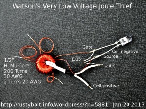
 I wound a half inch core with 200 turns of 30 AWG enameled wire and connected it up to a J105 JFET. The JFET doesn’t require a resistor, so there’s no power wasted there. I used two turns of 20 AWG stranded insulated wire for the primary (drain) winding, so the ratio is 2 to 200 or 1:100. I just about filled up the core, not much room left for any more turns. The LED was an aqua or blue-green that needs about 2.8 volts for full current of 20 mA. The core was out of a network board of a PBX. It’s high permeability. The curlycues are the splices at 50, 100 and 150 turns. The winding was tedious, and took awhile – that’s why I broke the windings up into smaller 50 turn pieces. The JFET was connected with the LED across the source and gate, with the cathode to the gate so it lights when the gate goes negative.
Note: Connecting the LED to the source and drain – like a normal JT – would not light the LED. Since the turns ratio is 1:100, if the peak voltage across the primary winding could rise to 3 volts to light the LED, the peak voltage across the feedback winding would then be 300 volts, and that would seriously damage the JFET.
Results
I used a power supply with a ten turn pot so it could easily go down to below a quarter of a volt. In the first iteration I had 150 turns and it just barely glowed at 160 millivolts supply V. I decided to wind another fifty turns on to go down even further. With 200 turns, the LED barely glowed at 125 millivolts, however the scope showed it was still oscillating well below that, clear down to 60 millivolts. The JFET just doesn’t develop enough voltage to light the LED. The frequency was highly dependent on the supply voltage, but at one point it was about 8500 Hz.
Conclusion
I feel confident that if the wire was smaller or the core was larger and I could get more turns on the core, the JFET would be able to drive the LED at even lower voltage. I think I’ll try for a larger core because the 30 AWG wire is about as fine as I want to work with. Even then it tended to kink and tangle. Besides, if I use a larger core I can wind some of the wire onto a bobbin that will pass through the core and I won’t have to have any splices. The only problem is that the thinner wire has higher resistance and since the load is driven by the current from the thinner wire, the current will be lower than if it were heavier wire (the LED doesn’t get much brighter above a quarter volt). But in order to get a higher turns ratio, the core is going to need more than two hundred turns; probably three or four hundred.
This is the first time I’ve done any real experimentation with the J105. What I had in mind this time was to get down to 40 millivolts so I could connect it to a thermocouple that I discussed earlier. But right now, I could get a decent glow by connecting four or five thermocouples in series for 160 millivolts. I’ve had the J105s for awhile but I really didn’t do much before, mainly because I knew I had to wind a lot of turns and it’s tedious, time consuming and BORING. But now that I got it to go down to 1/8 volt, I may take some more time and do another coil. However my earlier blog was doing about the same with the TN0702 and a button cell. And the LED just didn’t barely glow; it was drawing 45 mA and the LED was a lot brighter.
Update Jan 20
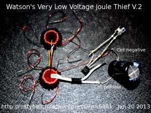
Everything stayed the same except I added two things (see the picture). I added a 2200uF bypass capacitor across the supply lines. I wound another coil with 200 turns of the same 30 AWG wire. Again I wound it in four sections and connected all sections in series. I then coupled it to the original core with a heavy wire link. I got the phasing right the first time; I tried it the other way and got no light at all.
 Results – I guess the words would be less than I had expected. When I powered it up, the LED again lit at about 125 millivolts. No change from the original circuit. However, when I looked at it with the scope, the circuit started to oscillate at 31 millivolts, about half of the original circuit. That would make sense because I have effectively added twice the number of turns to the feedback winding so it should be able to oscillate at the lower voltage. I’m pleased to see that it will work at such a low voltage, but disappointed that the LED did not light at a lower voltage. I have no explanation, but it might be that below 1/4 volt, the different metals coming in contact with each other, such as solder and copper, cause different voltages that tend to disturb the circuit. Another possibility is that the J105 just can’t put out enough current at that low voltage to light the LED. I want to try winding another larger core with more turns, maybe with finer wire to see if it will do any better. Right now, it’s doing much better than I had done before, so I can’t say that I haven’t made progress.
Update Jan 21
My speculation was right. I tried adding a second J105 in parallel with the original, and the LED lit at below 100 mV. Wow! So I soldered together two J105s in parallel and added them to the original and things looked even better. Double Wow! I got the LED to light at 80.5 millivolts, and the scope showed it started oscillating at 35 millivolts. That’s getting even better! The frequency was 5.8 kHz. If I had more JFETs I might be able to go even closer to the 40 millivolts I’m trying to achieve.
I was using clip leads – short ones, only4 inches long. By removing them and soldering the JFETs directly to the original, I subtracted about 5 millivolts from the LED’s turn on point, about 75 millivolts. I then scrounged up a fourth JFET and added it to the other three. Now the LED’s turn on point is about 78 millivolts, and the start of oscillation is 31 millivolts. But my scope and meters may be affecting the measurements. The supply current was about 100 milliamps.
A Summary of the Circuit at this point
Two coils link coupled, primary two turns 20 AWG, feedback winding totals 400 turns of 30 AWG wire. Four J105 JFETs in parallel. The aqua (blue-green) LED is connected between the gates and sources, with the cathode toward the gate. No resistor is used. Supply voltage is less than 1/8 volt.
Because the JFETs oscillate at much less than the LED light, I believe that the LED can be lit at a point nearly as low as the oscillation if the current through the JFETs is increased. I think that if enough JFETs or higher current FETs are added, the LEDs will light up somewhere near 35 millivolts. It’s a matter of finding a way to get the added current. I may try other types of FETs to get the higher current.
I have finished winding another larger coil, with 550 turns of wire. I will add another blog on this second version.
Back to experimenting…


i want circut diagram
I did not include a schematic because the picture of the parts and wiring diagram gives the same information and it is easier to understand for those who can’t read a schematic. If you use multiple JFETs in parallel and connect the LED as I showed, you should get good results. Click more than once on the pictures to enlarge them.