default

2013-03-08 Joule Thief Coil Wire and Measurements

Using a resistor in series with the LED or supply

The reason for using the 1 ohm current sensing resistor between the LED cathode and negative is that it has lower resistance than the meter.  The meter’s internal resistance varies depending on the range setting so one can’t depend on getting consistent readings between ranges.  One ohm is one ohm, and the number of milliamps is always equal to the millivolts on the DMM.  And a 1 ohm resistor costs a few cents and can be left in the circuit. and the meter leads connected to it only when necessary.

One other important thing: some may find they can buy a 1 ohm wirewound power resistor.  The resistive element is a winding and has a small amount of inductance, which may or may not affect the circuit.  It’s best not to use this kind of resistor.  Instead get the regular carbon film resistor, which has almost no inductance.

I Made My Own

But 1 ohm resistors are uncommon, so before I bought a bunch, I wound a short length of very fine wire onto a regular resistor and wrapped the fine wire around the leads and soldered them to the leads.  I’m not saying what the wire was because some of you wouldn’t be able to find AWG so you would use an equivalent SWG or metric size instead.  The copper wire tables tell how many ohms per thousand feet, which is the same as how many milliohms per foot, or in other countries milliohms per meter.  Some adhesive tape or clear nail polish will hold the wire in place.  I chose enough wire to give 1000 milliohms, and a resistor big enough to hold a few feet.

But the supply current was much greater than the LED current; something close to or more than 100 milliamps.  So I chose to reduce the length of wire to give a half ohm or even 1/10 ohm.  I just had to multiply the millivolts by the factor of two or ten to get the current.  The reason was that 1 ohm would give excessive voltage drop.  If the supply current was 100 mA, then the 1 ohm resistor would have 1/10 volt across it, and the supply voltage at the JT would be only 1.4 volts.  That’s 7 percent of the supply voltage – too much.  So using a 1/10 ohm resistor would reduce the error to less than 1 percent.

Coil Wire

I’ve been winding most of my JT coils with fine wire, usually 30 AWG but I’ve also tried finer (32 or 34 AWG) on some smaller cores.  I usually wind more than two (bifilar) windings, so that I can tie three of the four together for the primary.  The remaining single winding is the feedback winding.  This works well, and the length of the wire on smaller cores is less than a foot or 300 mm.  I measured the inductance of these and they are typically anywhere from 150 microhenrys to 600 uH – that is plenty for a JT.  The secret of the coil’s inductance is described here (scroll down to Stored Energy), and in my blog (scroll down to The math).


default

2013-03-07 Low Current Supercharged Joule Thief

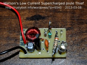
I told Paul about my Supercharged Joule Thief but he had doubts about it having lower current consumption than a conventional Joule Thief.  Originally I had set the value of the resistor to give the optimum current through the LED, and it was about 1.5k, which was good for about 20 mA LED current.  But I had not tried to go lower than that when I experimented with the circuit.  I decided to try changing the value of the resistor to a higher value to see if the circuit was still better than the conventional JT.

I used my Supercharged JT Flasher board but with the flasher parts replaced with a jumper (see attached photo).  This turned the circuit into a Supercharged JT.  I put a 10k pot in series with the resistor but left everything else alone.  The diode was a standard 1N4148 and the original resistor was 1k.  The LED was a white one.  The capacitor was a 1000 pF ceramic disk.  The transistor was a TN3019A, a plastic equivalent of 2N3019A.  It’s similar to the 2N2222A but higher power.  I put a 1 ohm resistor in series with the cathode of the LED to allow me to measure the LED current.

I applied 1.5V, and I adjusted the supply current for 25 milliamps.  When I measured the LED current I got 9.4 milliamps, which was about half of the optimum LED current I try to get to the LED.  I removed power and measured the pot, and found that it was set at 2650 ohms.  I removed the pot and soldered a 2.7k resistor in series with the existing resistor for a total resistance of 3700 ohms.  I applied power and checked the supply current at 1.5V and it was still 25 mA.  I measured  the voltage across the 1 ohm resistor and it was 9.4 millivolts which was the same as 9.4 milliamps.


Thus the efficiency is 3.3V x 0.0094A divided by 1.5V x 0.025A.  My calculations showed that this was 82.72 percent efficient, which is a lot better than a conventional JT.  I did not try to optimize the circuit for the lower current, but I think I could have tweaked it a bit to improve it somewhat.  The Supercharged Joule Thief circuit is a solid performer, and better than the conventional Joule Thief (see my comparisons here).


default

2013-03-06 Ecosmart 40W Equiv LED Light Bulb Disassembly

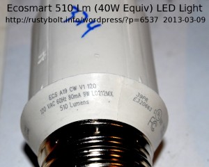
I bought an EcoSmart 40 watt equivalent LED light bulb from Home Depot on sale for under $12, regularly $20.  It is very similar to this one (I couldn’t find it on Home Depot’s  website).  It was a bright white, which seems to be the only color they have on the shelves.  Apparently all of the warm white LED lights sell out soon after they’re put on the shelf.  I got it just to see what’s inside, since I already have more than a dozen of the Philips L Prize LED lights.  One thing that mystified me was that the package said it was 8 watts, but the light itself was labeled 120VAC, 80 mA, 9 watts.  Now 120 Volts times 80 milliamps equals 9.6 watts.  I’m just wondering which of the three is the most accurate.

I think every LED light I’ve examined has had a largish heatsink, typically made of heavier metal, maybe zinc.  The LEDs really need it when they’re in a fixture which typically has no ventilation, since almost every fixture was designed for incandescent or filament lights which work just fine when they’re really hot.  It’s the same with this EcoSmart light.

I pried the flattened out plastic diffuser cover off of the finned metal heatsink by sticking a small screwdriver into the places where there was a space for the plastic tabs to catch on the metal.  I got it off without damaging any of the plastic tabs. This diffuser consisted of two parts; the flattened globe itself, which was translucent, and loose inside was an opaque white reflector and diffuser.

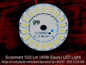
Inside was a disk full of surface mounted LEDs, each one rectangular in shape and they were all mounted in a circle just inside of the edge of the disk.  The LED light came straight out of the LEDs toward the end of the bulb and the opaque diffuser reflected most of it 90 degrees outward toward the circumference of the bulb.  I think this was not a very efficient way, since the diffuser absorbs some of the light.

In the middle of the disk was a thick plastic washer with a bite taken out of it for the two solder joints for the power pins.  It was held on with a pop rivet, so I drilled out the center of the pop rivet and it came off.  I removed the plastic washer, which had white heatsink goop on it, so it was beginning to get messy.  The disk was still held firmly against the finned heatsink.

I unsoldered the two power pins by sucking out the solder with a solder sucker.  When the pins were free, the disk came off easily with lots of messy white heatsink goop.  I used up several paper towels getting rid of all the white stuff.  Luckily it was still new, and not all baked on like often happens with a typical power transistor and heatsink.

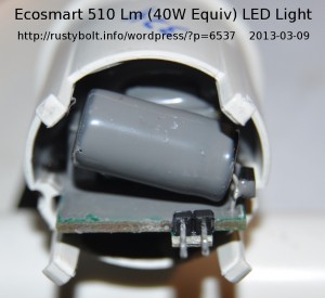
The two power pins projected through a hole in the finned metal heatsink, so I couldn’t see much down below.  There were four plastic tabs engaged to the heatsink so I got four small screwdrivers and pried the tabs away from the heatsink.  When the fourth one came free, the heatsink started to slide off the plastic base, where all of the circuitry was located, along with the bulb’s screw base.  I removed the finned heatsink, and the cylindrical base was exposed, and I could see inside of the base where all of the components were.  But I was disappointed to find that they were all covered in a thick layer of gray epoxy, sealed inside of the mess.  That was apparently why the bulb said that it was suitable for damp locations.

I was planning to be able to trace out the circuit and find out how it worked.  But it’s all covered up, and without a chisel and hammer, I probably can’t do anything with it.  I will try to measure the voltage when the power pins are connected to the LEDs, but that’s about it.  I could mount the LED disk on a flat surface, big enough to sink away the heat.  Then I could run a pair of wires from the disk to the power pins, which would be located where there was more room.  I could mount a few of the disks on the wall, and run the pairs down to the floor to a set of sockets.  But the light would be very bright, since the plastic diffuser would not be there.  Also, the LEDs are probably not isolated from the 120VAC power, so the disks would have to be insulated and protected from contacting anything.

Update Mar 8 – I examined the disk with the LEDs, and connected it to the power supply.  I found that there were two halves of the circle, each filled with 9 LEDs in series.  These halves are connected in parallel.  The circuit board where the pins come out was conveniently marked with a + and – so there was no doubt about the polarity of the DC.  When I turned up the power supply, the LEDs started putting out bright light when the voltage got up to the 28 to 30 volt range.  The current was several hundred mA.  But I didn’t know how much current should be going through the LEDs, and the disk was getting hot really fast with no heatsink, so I shut it off.

Update Mar 17 – I bought some paint stripper that was supposed to strip epoxy, and poured a half cup into a glass jar.  I put  the base  into the glass jar, with the epoxied end down, and let it soak for several days.  I pulled it out, wiped it off, and sawed slots along the side, lengthwise.  I pulled the metal screw base off and snapped it apart, and got some of that stripper on my hands, and it started to sting.  Washing my hands helped, and I managed to get the circuit board out.  I used a small nail to pry out bits and pieces of the epoxy, which was softened into a rubbery like consistency, sort of like an eraser.  Most of it came out of the cracks and off the circuit board.  I was surprised that the stripper didn’t damage the board or the parts on it.

default

2013-03-05 1.5V to 9V DC-DC Converter For DMM

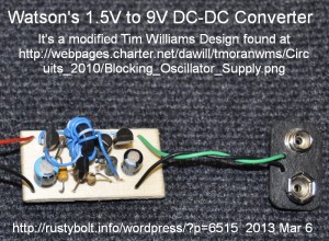
I built this 1.5V to 9V DC-DC converter. It’s a modified   Tim Williams design.  It’s a Joule Thief with the output rectified and filtered, which is compared to the “Vref” zener diode and if the output voltage is too high, it turns off the base bias current to the Q2 driver transistor.  The input is 1.5V (I’ll use an AA cell), and the output is 9.1V at less than 10 milliamps for a cheap DMM from Harbor Freight.

My (very few) Mods

The circuit is a solid, well designed circuit so I didn’t have to do much.  I used a 2N3906 for Q1, a PN2222A for Q2, and a 2N3906 for Q3.  I used a transistor with its collector lead cut off for the “Vref” zener diode.  Its emitter to base junction breaks down at about 8.5V, which when added to the 0.6V base to emitter voltage of Q3 give about 9.1 volts output.  He gave no information about the coil, so I wound a small toroid with 14 turns of 24 AWG telephone wire for the primary and 7 turns of the same for the feedback winding.  The core was a YR41003TC from Surplus Sales, which cost about 40 cents apiece.

I changed the 22 ohm resistor to 47 ohms; I decided that it would reduce the possibility of the ringing caused by the inductance and the capacitance of the transistor’s base.  I want to have as little RF interference as possible.  I changed the 10 uF output filter capacitor to 47 uF, mainly for the same reason.  The Schottky diode was a 1N5817 1 amp rectifier.

I built it on the small piece of birch plywood, by drilling the holes with a #60 drill in a small pin vise.  I had one of these at home, but at work I had a #60 drill, but no pin vise.  So I cut off four inches of a chopstick, put it in a vise, and drilled the tapered end deep enough to hold all of the drill bit except for a quarter inch.  Now someone is going to have to try eating with a single chopstick! (just kidding, they’re free at the Asian food restaurants).

The parts went in kind of haphazardly because it was my first prototype and things just had to be guesstimated.  I connected up a connector from a depleted 9V battery to the green output leads.  Later I’ll add a battery holder and switch to the red 1.5V leads.

I powered it up and measured the performance.  The output was 10V, too high.  I cut out the zener transistor and grabbed another one and soldered it in.  The new output voltage was now 9.1VDC, which is just what I wanted.  I measured the supply current with no load on the output and it was about 25 mA.  I connected a 1k resistor to the output and the output voltage dropped to 8.95 volts, not too bad for a cheap regulated converter.  That gave me about 8.95 milliamps through the 1k resistor.  The supply current had jumped up to 130 milliamps.  Any load current more than this and the output voltage drops quickly.  This converter was not made (and not meant) to have as much power as that needed for running a transistor radio or similar.  They require three or more times the output current.  Also, my experimental results with DC-DC converters used to power AM radios were disappointing: the AM band was filled with the RF interference from the converter.  FM band worked okay, though.

It’s working okay, but I’ll have to see how it works when the DMM is connected to it.  Sometimes the device is sensitive to RF interference and EMI (electromagnetic interference) coming from the battery.  After all, the normal 9V battery is pure DC, nothing else, so the device doesn’t have to filter it at all.  I was looking through these DC-DC converter circuits earlier, and I saw one that operated at 1000 Hz.  Well, if it was used to power an audio device such as an earphone amplifier, the power supply’s switching frequency is right in the middle of the audio band, where the ear is most sensitive.  Even the smallest amount leaking through to the amplifier is going to be heard in the headphones.  It is much better to have the converter working at some high frequency above the audio range to make this situation less objectionable.  Although I didn’t measure it – the frequency changes with the load, this Joule Thief converter is operating at some frequency in the several tens of kHz, well above the audio band, so there’s no problem with hearing it.

Back to thinking about how many of these I’m going to need as the 9V batteries go dead in these cheap DMMs.  Problem is I sometimes go to Harbor Freight and buy another DMM when they’re on sale, so I really should just use the spare ones and cannibalize the old ones with the dead batteries.  But I don’t.  It’s odd, but I have had to repair more test leads than replace the 9V batteries.  In an earlier blog, I talked about making one of these, but instead I wired three CR-123 3V lithium cells in series and taped them to the back of the DMM, and they work great.

 Some Other Ideas

I’m now glad that I’ve done one, and all I have to do now is connect it to the DMM.  I’ve thought about two other enhancements that would be a benefit to this converter.  The best one is to add a timer that shuts off the converter after a minute or two.  The usual DMM measurement takes only a few seconds or less than a minute, and the auto shutoff would prevent depleting an AA cell.  Or alternatively I could power this converter off a rechargeable AA cell.  There are two downsides to this, the biggest is that the typical rechargeable Ni-MH cell loses 1 percent of its charge per day, so a month or two later it has to be recharged, even if it hasn’t been used.  And I can’t remember ever having a charger that will charge a single cell – that’s one reason why I considered using 3V in that earlier blog.  But the single AA rechargeable is only 1.2V, and that means the circuit will not be able to put out as much current with the lower supply voltage.  It would be better if the supply was two AA cells, for a total of 2.5 volts or so, which would also make the current drain less and the cells would last longer.  With rechargeables, the problem of running down the battery is no longer a concern, you just keep a spare set of charged batteries in the same area and swap them if they go dead.  With two cells, the converter would operate on a pair of AAA cells with no problems.  That would make the package lighter and smaller.

Also with a rechargeable pack, the pack could have a jack on it for charging the two cells.  The pack would not need to be opened to recharge the cells.  I don’t want anyone getting zapped by high voltage.  I would put a double pole, double throw switch on the jack, so while it’s charging, it would be disconnected from the converter, thus protecting against operating the DMM while it’s plugged in and charging.

Back to experimenting.

default

2013-03-03 Latest Few Flashers Built, JTs Too

Paul emailed and said he has built his 12th Joule Thief.  Man, this guy is Helen Wheels – an even dozen in a matter of a fortnight (or week or two, I forget which).

I’ve been puttering with the TE Flashers.  I made most of them on small pieces of “Woodsie” wood that I got from Michaels arts and crafts store.  I was getting low on the 3/4″ by 1-1/2″ size, so I stopped by their store to get some more.  But they were out of those, so I looked at a 4 by 12 inch piece of 1/8″ thick birch plywood, the kind used for building model airplanes.  I decided to buy one for a buck and a half, less than a soft drink at a fast food joint.  I sawed off a couple strips to make more squares.  Then I peeled off the label, which took almost the whole end, one third of the total board.   I managed to get the label off in one piece, but the board was covered with the sticky, gooey glue they used on the label.  I can’t believe they could cause such a big mess on something they know is going to be used on a model, where looks are so important.  It has already picked up dirt and dust, and I can’t paint over it with the clear sealer, so I’m going to go back and get my money back and see if they have any of the Woodsie wood pieces in stock.

The pieces I had already cut are going to get the parts for the TE flasher mounted on them.  I think they will be my fourth and fifth?  Whatever.  I’ll use yellow LED for the most visual impact.  The yellow LEDs measured 2.4V at 28 or so mA, so this circuit drives them with no problems.

I bought some LEDs of various colors including red from alanparekh.com a few years ago, and at that time I found that the blue ones all had bubbles in them.  I complained and he replaced them.  But because I had a bag of 100 of very bright red LEDs from superbrightleds.com,  I didn’t open the red LEDs from alanparekh.com until recently.  Now I find that the red ones put out a small fraction of the light that the superbright LEDs put out, and it’s too late to complain.  I think I’ve learned my lesson: to never buy any more LEDs from eBay sellers and the like, and stick with the big distributors even if it costs more.  I’ll get a lot better product in the end.

Update Mar 10 – Paul said that after he has run the cells down to less than a volt, he runs the JT using two almost dead cells in series.  I’ve been running more than a half dozen germanium JTs with cells less than a volt, and they run the cells down to less than 0.3V before the LED dims to darkness.  I have found that many of the cells leak, and I’m glad I put a piece of pressed board on the shelf, to save the shelf from damage.  It now has leakage spots all over.  Since I’m using small magnets to hold the wires to the batteries, there is no holder to be damaged by the leaking.  My thought is that if the cells had not been so run down they may not have leaked so often.  In the end the cells I’ve put on the germanium JTs are less than a hundred millivolts, and ready for the trash can.


default

2013-03-01 Wire And Coil Winding Explained

I have heard people call the turns of a coil “wraps”, as if it’s a tamale or fast food or something.  Well, it’s not, even though that may sound delicious.  Each time the wire passes through the center of the toroid core, it is called a turn, even if the wire just goes through and doesn’t wind around the core.

The toroid with no wire on it is called the core.  Some people call the copper part of a wire a core, but it’s a conductor, because it conducts electricity.  When you wind two wires on the core at the same time, it is called bifilar wound.  I have wound 30 AWG fine enameled wire on a core with as many as five wires at the same time, which should be called pentafilar, but is probably written as 5filar.  Three would be called trifilar, and four would be called quadrafilar.  Winding more smaller wires onto the core instead of one big wire is easier because the wire is more flexible, which is the reason why they don’t use solid wire in the power cords, which have to flex a lot, where in the walls, the wire is solid and hard to flex.  There is another good reason why more smaller wires is better but I’ll leave that for later.

The wire is usually made of a solid strand of copper, called the conductor, with insulation made of an enamel coating.  The enamel coating is thinner than plastic so more turns can be put onto the core or bobbin.  More turns means the core can have higher inductance.  It also means that heavier wire can be used for lower DC resistance and less loss.

Using wire with insulation other than enamel coating is okay, it just means the core will not be able to have as many turns or as thick a conductor.  The toroid core may not have as high a performance as one with enamel insulation.  But it may be good enough for the application.

I often use wire I scrounged from telephone cables.  The wire is typically 24 AWG (American Wire Gauge) solid conductor, with a coating of PVC plastic insulation.  Two types if telephone wire are often available.  One is called crossconnect wire, and is typically two wires twisted together.  The typical colors are one is white with a blue strip and the other is blue with a white stripe.  These can easily be separated by unwinding the wires and rolling them up separately, or else just leave them together and cut off a short length for use.  The other type of wire is called IW, for Inside Wire.  It has four of the twisted pairs, each a different color.  They are covered with an outside jacket.  The wires typically have a thin piece of thread which sometimes looks like angel hair, and this is used for ripping through the jacket so it can be removed.  Several inches of the wire is stripped off the end.  The length of IW is clamped in a vise or tied to a doorknob, and the thread is wound around the shank of a screwdriver and then pulled along the wire.  As it rips through the jacket,  it is wound up.  Close to the end it may pull out of the jacket, but by then the jacket should also pull off the wire.  This leaves the four pairs of wire bare and then they can be wound into hanks for later use.


default

2013-02-28 Website Of A German LED Distributor

I found this LED website in Germany,  I like it because it’s LEDs, LEDs, and more LEDs, and not an electronics parts distributor.  The LEDs are broken down into various types, standard, high power, etc., etc., etc.  I’m looking for a similar website of a store in the U.S.  I figure it would be best to order from a U.S. LED specialist since the shipping would probably be cheaper.  And it’s probably faster than from Hong Kong or China!


default

2013-02-27 CD-ROM Drive Motor Runs Joule Thief

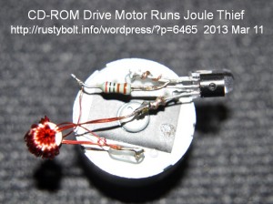
I had to spin the shaft really fast to get the LED to light up, and now that I converted the generator (was a CD-ROM drive motor) by adding the Joule Thief to the back, all I have to do is spin the shaft gently and the LED lights up brightly.  It’s a big difference; it’s much easier.

The coil uses a T231212T toroid core from Surplus Sales.  I ‘trifilar’ wound it with 6 inches of three conductors: two were 28 AWG in parallel for the primary and a single 30 AWG for the feedback.  The transistor is a BC337-40 and the resistor is a 2000 ohm, 1%, 1/4W I salvaged from a PC board.  I could have made all of it fit on the back of the motor if I had cut the leads shorter.

I was trying to come up with a way to mount the tiny generator onto something hand held, and put a crank on it to allow charging up a super capacitor.  I bought one of those hand crank flashlights and they don’t work; the LED goes out as soon as the cranking is stopped.  I think there must be a better way to charge up a multiple farad capacitor so that the LED will light brightly for several minutes.

Back to experimenting…

Tags:
default

2013-02-26 Flasher, 1.5V Switched Capacitor From TE

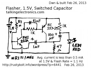
I found this 1.5V switched capacitor flasher circuit on talkingelectronics.com (I can’t get a direct link to it).  It flashes a red LED; I haven’t tried any other color but the similar Bowden circuit will brightly flash a yellow LED.  This is essentially the same circuit I blogged earlier, except this TE circuit uses only two transistors.  My measurements show that it is oscillating at about 1.1 Hz, and draws less than 0.5 mA average current at 1.5V. The circuit is still (not brightly) flashing at 1V, and can be barely seen flashing at 0.8V.  The red LED is what I’m measuring; other colors such as amber and yellow have a higher forward voltage and may flash brightly as long as the cell is fresh but may dim well before the cell is depleted.  Several of the yellow ones I built have bright flashes, but I haven’t checked how they hold up as the cell is depleted.

This circuit is essentially the flasher part of the Bowden circuit, without the third driver transistor.  I’m assuming (but I don’t really know how accurate that assumption is) that the flash is not as bright as my Bowden flashers, because the current draw is not as high.  I’m assuming this because the C2 in Bowden’s circuit is more than twice the capacitance, and R3 and R4 are less than half the resistance.  However the Bowden circuit has the additional transistor; that and the power dissipated in R2 may reduce the difference.

I made very few changes.  The original circuit used a BC547 and BC557, which are not high current switching transistors.  I used the ubiquitous PN2222A and the BC327-25 for the driver.  TE recommended that R1 be from 100k to 470k.  I have found that using a resistor lower than 1 Meg often causes this type of flasher circuit to stop oscillating when the supply voltage is at 1.5 or so volts.  I usually recommend that this resistor be 1.3 or more Megohms.  With that resistor, and a 1 uF capacitor it flashes about once per second.

This TE circuit puts out a bright flash and draws very low current, giving long battery life.  It’s simpler and cheaper than the Bowden circuit, but the difference should be accurately quantified so that the builder can make a judgment on whether or not the Bowden circuit has advantages that outweigh the added cost.  Still, the experimenter can build this circuit and expect good performance from it with red, orange, amber or yellow LEDs.  I tested one of the yellow LEDs for current and forward voltage.  At 2.4V, the current was almost 30 milliamps, and at about 20 mA the voltage was about 2.3 volts.

Update Feb 28 – Since the above, I’ve built a few more of this circuit.  It’s a bit smaller than Bowden’s flasher, since it has one less transistor.  I want to try experimenting with two flashers on the same board, driving a single LED.  I would like to get the LED to look like it’s flickering, similar to a candle.  This may require more than two flashers to get enough randomness to simulate the candle.  I think when I have a few more single boards built, I may try to wire them together.  More in the near future, I hope.

Update Mar 2 – I wired two of the boards together.  I removed the LED from one board and wired the junction where the anode was to the same point on the second flasher.  I really wasn’t surprised when I found that the two flashers synchronized so there was only a single flash.  The two  flashers are coupled too closely, so that most likely the faster one triggers the slower one to fire early when the faster one fires.  My idea has failed to produce the results I wanted.

One thing, I haven’t tried experimenting with the 10 nF capacitor across the 1k resistor.  Most circuits of this type that I’ve seen have no capacitor across the resistor.  If there is one, it’s usually much smaller than 10 nF.  But I have included it in every one I’ve built.  I have a bag of a few hundred of them, so I figured that it was almost no cost to put it in the circuit.

Update early Nov, 2013 – I have drilled and populated seven more boards for decorations during the Xmas holidays.

Back to experimenting…

default

2013-02-25 Regenerative Receiver Design

I received a Google Alert about this regenerative receiver schematic being posted to the RegenRX Yahoo Group (you may have to be logged on the view it).  It’s quite complex for a regenerative receiver – the average regen set has just a few transistors.  But its Achilles Heel is the front end.

When I was young I had a Tennelec Memoryscan scanner receiver that was quite an advanced design for its day.  I had it connected to a small discone antenna on the roof.  But after a thunderstorm it quit working.

I found that it had a 2N3904 or 2N3906, I forget which, for the antenna front end, and that had burned out.  The receiver started working again after I replaced it.  The simple conclusion was that it was a faulty design.  Putting the transistor right at the antenna input, with no protection against lightning, is not only a faulty design but it’s a safety hazard.  A component could catch on fire and burn down the dwelling.

A receiver that has an external antenna jack should have a filter at the antenna input with a very low resistance to ground.  If any fault currents appear on the antenna input, they will then be shunted to ground through the filter, which would have an RF choke with a low resistance coil of wire, for example.

One other point that I believe needs improvement is the use of a shunt regulator.  This wastes a constant amount of power, which shortens the battery life if it’s powered by a battery.  I think a low dropout regulator chip would be a better choice.  The voltage would be more accurate, too.


© RustyBolt.Info/wordpress
CyberChimps