default

2013-03-20 2W LED Light Is Equal To 60 Watts

I’m trying to figure out how these Miracle LED people get away with advertising a two watt LED light is equal to a 60 watt light.  These are supposed to screw into the sockets of a ceiling fan, and come in a set of four for fifty bucks when tax is included.

Also, they say 30,000 hours but the fine print says “up to”, their weasel words to get away from being sued when the lights don’t last that long.

default

2013-03-19 Two Transistor V Boost “JT” Using SMT Inductor

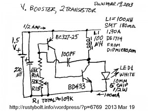
I got some SMT power inductors from dipmicro.com because I read that they were only 0.18 ohm and could handle almost 2 amps.  The winding is on a ferrite bobbin and that is covered by a ferrite sleeve to give it a better magnetic path.  But there is still an air gap between the bobbin and sleeve, which supposedly helps to store more energy (see here and scroll down to Applications).  They are sealed in epoxy and have two metal ‘feet’ that are soldered to the PC board pads (no holes are needed).  I had to solder two leads to them to connect it to my tack soldered circuit.

This is a standard two transistor PNP-NPN type V boost circuit often mistakenly called a Joule Thief.  I decided to use this circuit as a test circuit to try the different inductors I have purchased recently (see Note at end).  This circuit had previously run on the yellow-white iron core toroids I had blogged earlier.  I got better results – higher LED current – with this SMT inductor.  I started with a 1000 pF capacitor but I found that the 100 pF capacitor gave more current.  I also started with 68k, then added the 50k trimmer pot to adjust the base bias, and found that it had a broad peak that was a bit above 100k.  Apparently the base bias controls the circuit in a way that gives a peak to the LED current.

The BD433 is a power transistor with a plastic case that is totally insulated – there is no metal for contact with a heat sink.  It seems to work very well at 1.5V and high current.  It must have been switching quickly on and off since there was no sign of it getting warm.  I think I could put a 1k resistor from base to emitter (I’ve seen this circuit often with the resistor) and it may help a bit, without wasting much current.

Back to experimenting…

Note:  I’ve been experimenting to define a standard V boost circuit that uses commonly available parts  and will give a well defined performance if the experimenter sticks to the parts list.  I guess one could say it will be the next best thing to buying the circuit in kit form.  In this case I wanted to drive a white or blue 1 watt or more LED with a 1.5V cell, to where it will put out at least a half watt, but  somewhat adjustable by the builder.

default

2013-03-18 Through Hole Devices Are Becoming Hard To Get

I had no problems getting the 2SK170 JFETs from Futurlec.  They were on tape.  I don’t know what manufacturer, but they are not Toshiba.

Right now, I think a lot of the major semi makers are abandoning through hole parts, and going to surface mount only.  To get a through hole part, one may have to buy a large amount (a whole reel) or get the part from a maker such as KEC (Korea Electronics), BEL (Bharat Elec) or Rohm.

You can get the National Semi Discrete Data Book 1978 Edition (PDF) from Archive.org.  When you look up a transistor, it tells you the process that it was from.  In other words, the chip inside the transistor is sorted from the chips made by a certain process.  Some have higher specifications, for instance higher gain.  Thes may be sold as 2N3904.  The lower gain chips may be sold as 2N3903.  But they are the same chip, and if the circuit is not critical, you may be able to substitute the 2N3904 for the 2N3903.

If you look in the right hand column, you may find several different transistors that use the same process.   In the Pro Electron Series, you may find that the older transistors such as the BC107 were packaged in the TO-106 package, which is no longer made.  But you may be able to find an equivalent transistor, such as the BC547, using the same process in the TO-92 package, which is common and still being made.

Regarding the 2SK170.  It may not be recommended for new designs, but the replacement, the 2SK880, is not through hole, it’s surface mount, and that would mean redesigning the PC board.  So the assembler must use the 2SK170 until his supply of PC boards has been used up.  The alternative would be to try to find a substitute JFET.  If the JFET is in the Databook, you could find out what process is used, and then find other JFETs that use that process and try to find one that would substitute for the 2SK170.

I also got some 2N7000 MOSFETs.  They also came on tape, but the tape has the side toward the MOSFETs coated with aluminum foil.  This is to prevent damage from static electricity.  The MOSFETs are held onto the the tape with masking tape.  Normally the leads are cut off above the tape as the part is put into the PC board.  The masking tape is never disturbed.  But in my case, I don’t have a machine so I usually pull the part off the tape, and sometimes the masking tape pulls of with the part, sometimes it stays on the tape and the part leads pull free.  The problem here with the MOSFETs is they are more sensitive than JFETs to static.  That’s why there’s the aluminum foil.  And the masking tape is triboelectric.  This means when the tape is pulled off, it generates static electricity.  So by pulling off the MOSFETs I could be causing them to burn out.

What to do?  I could try to duplicate the machine and just cut the leads off above the tape.  But then the leads are shortened and obviously not the same as when they were made.  My thoughts are that if I squeeze the 3 leads between my fingers and pull the MOSFET off the tape, the static from the masking tape will go through my fingers and not damage the MOSFET.  Or should I try to cut the masking tape off before I pull the MOSFET off the foil?  I’ll have to experiment a bit to find out how each works.


default

2013-03-17 Ultra Low Voltage Joule Thief – More Experiments

My first ULVJT which used four JFETs in parallel was a success in that it put out light at supply voltages as low as 34 millivolts.  But it put out only a minuscule amount of light, and needed to be increased.  The next one I built had six 2SK170 JFETs in parallel. It used a bit more current than the first, but still not enough to brighten up the LED.  One of the Youtube posters said he put a ZTX1048A in the circuit to boost the current.  I added one of these to my circuit, and it helped somewhat but really wasn’t all  that much.

At the end of my blog I  talked about using a MOSFET, but that it needed quite a bit of power to drive the gate.  I decided to go with a much smaller MOSFET, the 2N7000.  This has less than 60 pF gate capacitance, compared to the thousand pF of a power MOSFET.  The low capacitance makes it much easier to drive with low power.

I tack soldered a 2N7000 MOSFET to the existing JFETs, source to source and drain to drain.  I connected the gate to the other gates through a 0.1 uF capacitor.  This is because the gate of a MOSFET must have a positive voltage on it, whereas the JFET needs a negative voltage.  I then connected a 470k resistor to the MOSFET gate to supply the positive voltage.  I connected the remaining end of the 470k to the center wiper arm of a 500k potentiometer.  One end of the pot was connected to ground and the negative of a fresh AAA cell.  The other end of the pot was connected to the positive of the AAA cell.  I now had an adjustable voltage source that could put from zero to 1.6V on the gate of the MOSFET.  Since there is no gate current, there will not be any voltage drop across the 470k resistor.

I turned the pot  down to zero and applied power to the circuit and the LED lit up when I advanced the supply voltage to 100 millivolts and decided this would be the supply voltage to do the tests.  The LED was lit but not brightly.  When I turned up the pot, all the way to its maximum, I could not see any difference in the brightness of the LED.  I shorted the MOSFET gate to the source to see if it was conducting current, and I saw no change in the LED, so the MOSFET was apparently not conducting current with 1.6 volts on its gate.

I needed more voltage than 1.6V, so I removed the AAA cell and clipped a power supply set at 3V onto the battery holder.  Now when I turned up the pot, the LED got considerably brighter.  Now I had the answer: the MOSFET needed more than 1.6V to function.

I had one obvious choice.  Just replace the AAA cell with a 3V lithium coin cell.  Easy peasy, and it will last forever since there was almost no current draw.  I could put a 470k resistor at the bottom end of the pot since I knew that the voltage would have to be higher than 1.5V, giving a total of 1 meg, so the battery current would be 3 microamps; so low that the battery will last its shelf life.

I got another brainstorm.  The circuit is already generating a small amount of current.  Why not just rectify the existing pulses, and use the resulting DC to furnish the gate bias?  I decided to use a voltage doubler.  That should give me the three volts easily.  I added a coupling capacitor, two 1N4148 diodes and a filter capacitor to rectify and filter the DC.  I thought that this would give enough voltage to do the job, but it didn’t,  It put out only 1.75VDC, just slightly more than the single AAA cell.  So I may have to add another diode to make it a tripler, and maybe replace the diodes with Schottky diodes to give less voltage drop.

I added a third diode and another capacitor to the doubler, and it made the gate bias voltage jump up above 3 VDC.  But when I put my DMM on it, I can see that the voltage sags from 3.3 or so volts down to about 3 volts.  The impedance of the tripler is so high that the 10 megohm impedance of the meter loads it down.

I set the supply at 100 millivolts as before.  With the tripler, the LED is brighter than it was before.  I would like to give an accurate amount but I can’t, all I can say is it is substantially brighter.  When I ground a point in the tripler and cause the gate bias to be zero, the LED dims substantially.  When I remove the ground, the LED lights up substantially brighter.

I noticed that the minimum supply voltage has changed from below 40 mV to about 45 mV, but as the voltage rises from 45 to 100 mV, the LED gets much brighter, much faster.  This 5 millivolts difference may be caused by the voltage  drop in the supply cables and wiring, due to the increased current draw with the MOSFET working.

Conclusion – The circuit as it is, with four JFETS, a single MOSFET and a few capacitors and diodes is much better than the original circuit with just the JFETs alone.  I am not using any gate bias battery, the circuit is stand alone, making its own gate bias for the 2N7000 MOSFET.  I’m not going to go any further than I have in developing this circuit.  But if I decided to go for it, I would remove a few of the JFETs and replace them with the MOSFETs.  The supply current and LED current would be increased even more.

Previously I had another very low voltage Joule Thief blog, but it used regular transistors.

default

2013-03-16 Inductor,Toroid, 470.0 uH,2.3 IDC,0.19 Ohm

I bought some Jameco inductors, among them was Jameco Part No. 371215, which was a closeout sale of $.49 each.  Their picture shows it as uncovered wire, but all of the ones I  got had a black heat shrink tubing around the circumference.  The wire diameter was 24 mils, or about 23 AWG when the enamel insulation is removed..

I measured one and it was 475 uH.  I cut off the HS tubing leaving the bare wires.  The winding was more than one layer, so I started unwinding the turns, with the objective to leave a single layer that was at least 100 uH.  I removed about a meter of wire and left a single layer.  This layer was 64 turns, 0.078 ohm DC resistance, and measured 150 uH.

The core was painted yellow with a white end.  The core measured 0.81 inch O.D., 0.45 inch I.D., and 0.265 inch high.  I believe this is an iron core, mainly because it has low permeability.  I don’t remember ever seeing a ferrite core painted yellow.  The data sheet said ferrite core, and the core is from Core Technology and is a TC80-26B.  I could not find any information online for this company or product.  I strongly suspect that they mistakenly put the word ferrite in the data sheet.  I did find this at surplussales.com which says that the Micrometals yellow-white iron powder core is 26 mix, which is consistent with the datasheet.

The price seemed reasonable.  The toroid is a bit large for a Joule Thief, but it’s easy to work with, and makes winding a second feedback winding easy.  It could hold more turns and with two more windings could be used for a higher voltage DC to DC converter.

Since it was a closeout sale, they may no longer stock these when they have sold out.  However they have various similar inductors that look like they use the same core.  For many experimenters a 220 uH, 330 uH or similar would be just as good for a JT, and it will probably have heavier wire, which keeps the DC resistance low.

Another different inductor

I also bought some of these inductors in their closeout sale.  These are larger than the first inductor, but the number of turns is less so the inductance is 180 uH.  These also use the yellow – white core.  The number of turns is 44, and the wire size is 35 mils or 20 AWG when the insulation is taken into account.

default

2013-03-15 “Joule Thief” Powered By .040 V Thermocouple

Click more than once to enlarge

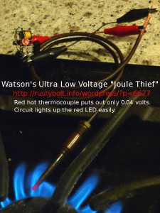
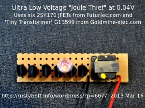
I’ve been interested in very low voltage converters for quite a while.  I blogged this document several years ago in my late great watsonseblog.  Almost a month ago I was commenting on a circuit, often called a Joule Thief, that was powered at 27 millivolts by a Peltier junction and the heat from a guy’s body.  They said that the 2SK170 JFET was the best choice for the circuit.  I had ordered the G13599 tiny transformers from Goldmine-elec.com and I wanted to try them with some of these 2SK170 JFETs to see if the circuit’s LED would still be putting out light at the 40 millivolts that my thermocouple put out when it was hot.  I ordered the 2SK170 JFETs from Futurlec and I’ve been waiting for a month for them to arrive.  Finally today they came in the mail.  They were all on tape, cut into lengths of ten JFETs each.  Each JFET was marked “K170 BL 1C”, which means that they were 2SK170, with the Idss range BL, which is the middle range of 6 to 12 milliamps.  I don’t know what 1C means, might be the manufacturer code.

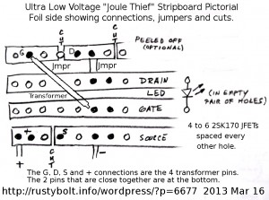
In the original Youtube video the circuit used four of the JFETs in parallel to get increased current.  So I soldered four of them to some wire leads to connect all sources, gates and drains respectively together in parallel.  Goldmine shipped a paper with the pinout of the transformer along with the parts.  I connected the low resistance winding to the drains and supply positive.  I connected the high resistance winding to the gates and supply negative.  I connected the LED between the gate and drain, with the cathode (flat spot) to the gate.  There is no resistor in my circuit because there is no current flow into the gates, so they don’t need a resistor to limit the current.  I added the 470 uF capacitor across the supply leads; it’s optional but I highly recommend that it be used.

The first time I tried it I found that the high resistance winding was connected backwards and the LED would not light.  I reconnected the winding correctly and the LED lit brightly at a half volt.  I kept reducing the voltage and it was still glowing at well below the 40 millivolts I was hoping for.  Success!  I’m getting the same performance as the original circuit in the video.  All I need to do is put another 10 or more of them (a lot more?) in parallel to get the increased current.  But then I should try to get this circuit to generate enough voltage to drive a power MOSFET and let it do the heavy lifting.

I still have to do a good closeup of the circuit.  Some call this a Joule Thief, but it bears very little resemblance to the original JT.

Click more than once to enlarge

Update Mar 16 – I connected it up to a peltier junction.  The palm rest area on my laptop next to the mouse pad is warm, so I put the peltier on there with a piece of aluminum as a heatsink and radiator.  Now the LED glows from the warmth of the laptop.  The voltage measured 34.2 millivolts.  I have to find a larger piece of aluminum to take away more of the heat, and make the LED brighter.   I’m building a neater version on a piece of stripboard (see photos).

Veracity of photos – These are the actual photographs of the circuit running from very low voltage sources: less than 0.1 volt, typically below 50 millivolts.  The photos have not been “tricked out” with Photoshop or any software to disguise any external power sources.  They are the real thing.

Click more than once to enlarge

I’m starting on a third one.  I did some measurements and noticed some odd behavior.  The current increases as the voltage increases, up to 0.95V, then as the voltage increases, the current decreases, which is the opposite of a normal Joule Thief.  The current reaches a maximum then will not go higher, which is typical of JFETs, since they are constant current when the gate is at zero volts.  Also, the frequency is about 8kHz at the 40 millivolt point, and steadily decreases as the voltage rises, down to 240 Hz when the voltage is at 1.5V.

I added a ZTX1048A – I connected the emitter to the sources, the collector to the drains. and the base through a 1k resistor to the gates.  I saw a definite increase in brightness when I connected the base, but I’m using the one with four JFETs in parallel.  I noticed two things.  The added ZTX1048A does not reduce the lowest point where the LED goes out.  It’s still about 35 millivolts.  And it doesn’t change the plateau that is reached when the voltage is increased.  Perhaps if I remove three of the four JFETs and use only a single one with the transistor, it might do better.

But I think I should not be trying to increase the JFETs’ output.  Instead, I should use the circuit as-is, as the bootstrapper, to get the voltage to start a power MOSFET up, and then let it take over.  Once the MOSFET gets going, there is no limit to the amount of power it can boost from a very low voltage.  I have some IRLZ34s with about 30 milliohms internal res.  That would allow about 1 amp from a 40 millivolt thermocouple.   But it takes a bit of AC current to drive the gate, and that’s where things are a problem.  Maybe use the JFETs to charge a 1000 uF capacitor, then get it start up the MOSFET which will bootstrap itself into running.

Or perhaps I should add a 2N7000 MOSFET to the circuit to see if it will help.  It has only a few tens of pF gate capacitance compared to a thousand for the power MOSFETs and therefore is much easier to drive.  Update Aug 2, 2013 – I’ve been experimenting with the 2N7000 to find out if I can get it to perform at very low voltage.  Do a search of my blog for 2N7000 to see a circuit.

default

2013-03-12 No Toroid Joule Thief 4 From Xee2

I was watching a Youtube video of Xee2vid’s no toroid Joule Thief 4, which is a conventional JT that uses a Radio Shack 273-1380 audio output transformer (Xee2 doesn’t allow comments).  The ad doesn’t say what the specs are but IIRC, it’s a 1000 ohm center tapped primary and an 8 ohm secondary.  The small size means it can handle only a few hundred milliwatts.  Also, since it’s an audio transformer, it’s most likely that the frequency is going to be much lower than a normal JT, possibly in the audio range.

The schematic shows that the secondary is connected to the battery positive and the collector of the transistor.  This 8 ohm winding most likely has a DC resistance of several ohms, but I don’t know absolutely since I’ve never measured one; I’m just going by my previous experiences with this kind  of transformer.  The center tapped winding is higher DC resistance but it’s of no concern since the current is minimal.  One concern is the ratio of the two windings.  The voltage across the center tapped winding is substantially higher than the 8 ohm winding, I think it’s the ratio of the turns, which is the square root of the impedance ratios.  So 1k / 8 is 125 so about 11 to 1.  But it’s half that because only one half of the winding is connected.  That would be about 5 or 6 to 1.  For every volt on the 8 ohm winding, there would be 5 or 6 volts on the half of the center tapped winding, which may be high enough to exceed the maximum emitter to base breakdown voltage for the transistor.  As I’ve shown, this can damage the transistor.

One way to get around this is to use only the secondary and not use the 8 ohm winding.  The battery positive is connected to the center tap and one end goes to the collector, the other end goes to the resistor and capacitor.  The DC resistance of the winding is going to reduce the collector current, but it will always light up the LED because you can’t get the connections wrong.

Another concern is can the 8 ohm winding with several ohms DC resistance conduct enough current to fully light the LED?  Probably not.  There may be nothing wrong with this if the builder is not concerned with getting the most out of the circuit.  But it would be an obstacle for those wanting to get the JT to its maximum performance.

All in all, using this transformer for the coil in a Joule Thief is an easy way to get started.  But it’s definitely not the best way to make a JT.

default

2013-03-11 Quadrifilar Winding A Joule Thief Coil

The typical JT coil is wound bifilar, two windings at the same time.  Winding the wire at the same time makes it easier, and it’s electrically the same as if two separate windings were wound.  I often use 24 AWG wire and wind the coil bifilar.  But I also wind it using four pieces of wire, I’ve seen this called quadrifilar winding.  The advantage is that the wire can be smaller, and easier to wind.  And the resultant four windings can be connected as if they are bifilar, or as in the case of the drawing, three of the windings can be in parallel for the primary, and the fourth used as the feedback winding.  The advantage is the three windings have a lot less DC resistance than a single winding, and a lot less loss due to that resistance.

default

2013-03-10 Comparison Of 2 Transistor V Boost “JT”

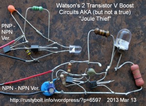
I have built a number of the two transistor “Joule Thief type” V boost circuits, and they work okay.  I am comparing the two typical types: the PNP – NPN and the NPN – NPN types.  The common one is the PNP – NPN type which uses a PNP transistor for the first transistor and a NPN type for the second transistor.  With the collector of the first transistor driving the base of the second transistor, there is no need for the pull up resistor needed in the NPN – NPN type.

Not only does it eliminate one resistor.  The PNP – NPN type also drives the second transistor with as much current as it needs, where the NPN – NPN type needs to have a low value resistor to supply enough current to the second transistor’s base to keep it in saturation, AKA fully turned on.

default

2013-03-09 Light Deactivated Joule Thief

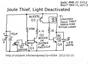
I built this up – tack soldered it together – before I drew the schematic.  My intention was to make a circuit that was very low on power when the light deactivated it, and to use parts that the neophyte experimenter would already have.  I wasn’t concerned about complexity or cost, but the three extra transistors, resistors and LED are relatively inexpensive.  As I said, the experimenter may already have them so it wouldn’t be any added expense.

Some experimenters connect a CdS photocell across the base to emitter of the Joule Thief transistor.  This shunts all of the 0.9 milliamp base current from the 1k to negative when light hits it.  Thus during the daylight hours, the circuit is still drawing nearly a milliamp, which is much less than the 50 to 80 mA during normal operation, but it is still substantial and would discharge the battery over a few months.

My choice was to not use a CdS photocell because they are much more expensive and difficult to obtain than a LED,  resistors and transistors.  Because the LED puts out so little current, it must have more than one transistor to multiply the current up to enough to turn the other transistors on or off.  Also, the sensor LED’s current output must be inverted so that it shuts off, rather than turns on.

Another characteristic of a CdS photocell is that the resistance is somewhat linear with light hitting it.  It doesn’t have a “knee” like a diode has.  As the light hitting a LED gets brighter, the output voltage finally gets to the point where it will reach 0.6V and turn on the transistor.  This helps make the deactivation more decisive.  With the CdS photocell, the resistance could decrease in a bright ambient light, but the circuit could continue to run, and all the current through the photocell is just wasted.  There is a way to change this, it’s called a Schmitt Trigger.  But this just adds complexity to the circuit with no significant benefits.

Circuit function

Normally the feedback winding would be connected to the positive, here it is connected to the collector of a PNP transistor.  During normal operation with no light on the sensor, the sensor LED and Q1 are open, and the 470k turns on Q2 and its collector current turns Q3 fully on, so it is as if the feedback winding is connected to positive.  The Joule Thief operates normally.

When the ambient light hits the sensor LED, the small current generated turns on Q1, which shunts all of the current from the 470k to negative.  Q2 turns off, and Q3 also turns off, and no longer lets current enter the feedback winding.  The Joule Thief cannot operate without the current to the feedback winding, and it turns off and the LED goes dark.  The amount of current drawn while the circuit is disabled is only microamps – just the current through the 470k.

How well does it work?

The circuit works just fine.  When there is no ambient light, the voltage drop across the Q3 is only .036 volts.  That’s low enough to make it look like the feedback winding is connected directly to the positive.  There is no discernible difference in the LED brightness when I short across the Q3 – if you short Q3 E to C, it’s just a regular Joule thief.  The light sensor is not very sensitive and has to be held about a foot away from my white LED task light to turn it off.  But this is very dependent on the type of LED used and the gain of the transistors, especially Q1.  In my case I used an amber LED that did not put out much light, and I think that it would be more sensitive if the LED was a superbright red LED.  The circuit will usually turn off when it’s outside during daylight, due to the light being much brighter than the indoor lights.  There’s a lot of room for experimentation with different transistors and colors of the LED to get various light sensitivities.  The JT is just a run-of-the-mill everyday conventional JT, so the LED’s light output is dependent on what and how it’s made.

© RustyBolt.Info/wordpress
CyberChimps