default

2013-10-23 Smooth Joule Thief

IMG_20131023_193647

Click more than once to enlarge

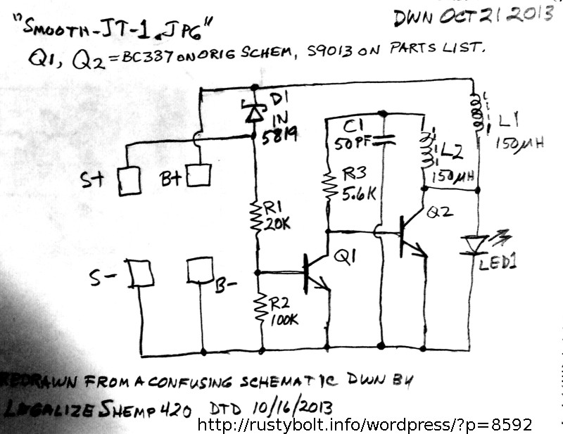
I came across a schematic of a “Joule Thief” circuit, actually a two transistor LED V boost circuit, on OverUnity.com.  This is part of a garden light, and has a solar cell to recharge the battery, and the battery to store the electricity until after dark.  The schematic, dated 10/16/2013, was drawn partially upside down and it was confusing to understand how it worked.  I redrew it according to more conventional ways of drawing a schematic, such as input on the left, power at the top, common or ground at the bottom and output on the right.  I checked and double checked my drawing to make sure it was the same as the original.

The first problem I saw was that the Q1 base bias did not look like it would work.  The R2 100k resistor is connected from the Q1 base to common negative, which is okay.  But the R1 20k resistor is connected to the positive of the solar cell.  This might have a positive voltage when the sun is shining, but that is when the light should be off.  Then after dark, there is no voltage across the solar cell, and no positive voltage across R1 to supply base bias current to Q1.  So I don’t see how the light would work at night.

The D1 1N5819 Schottky diode is connected from positive of the solar cell to positive of the battery, but it conducts only when the sun is shining.  After dark, the D1 is reverse biased and conducts no current to the R1.  It should be effectively an open circuit.

I checked the data sheet for the S9013, and found that it’s capable of handling a half amp, which is about the same as the 2N4401 or PN2222A, and also has the same pinout.  There are several gain ranges, and if I had a choice, I would pick one of the higher ones when purchasing them.

The circuit is similar to other two transistor circuit designs, however almost all two transistor designs use a single choke, but this circuit uses two chokes.  This is one of the more expensive components in the circuit, so eliminating the second one would save money, unless there is something important that it does in the circuit that would justify keeping it in the circuit.  Apparently other circuit designers didn’t think it was necessary or important.

I’ve thought about the possibility that Q1 does nothing while it’s operating, and is only there to turn it off during the daytime.  If that is the case, the only way that it can work is if the two chokes are acting as one coil with the external magnetic field coupling them together.  The two chokes are close together, but they are positioned end to end, not side by side.  The coupling while end to end is not as good as if they were side by side.  I have built one of these before but I consider them to be a poor design, because the circuit may work poorly or not at all if the two chokes are positioned wrong, are polarized wrong or have been wound differently.

I’m intrigued by what might be happening with this circuit, especially with the function of L2 and C1.  I’m seriously considering putting the circuit together next weekend, but I’m pretty sure that it will not work with the bias problem.  I thought that the author may have made a mistake when he drew the schematic.  I have considered trying to contact the author on OU, but decided against it.  I only log onto this OU forum once every few months, and in the past it has deleted my account because I didn’t log on often enough.  Or else it required a “secure” password and complained when I tried to use one of mine, so I had to choose another and I don’t have a snowball’s chance in hell of remembering it after a few months.  And I’m sick and tired of having to jump through so many hoops to recover my password that I’ve decided not to waste time doing it again and again.  So that’s why I’m posting it here.

Update Oct 27 – Hanspeter left a comment and gave a link to the circuit (in German) (I ran it through Google translate). Thank you, Hanspeter, for showing us another almost identical circuit that uses the same principles.  The author confirms my assessment that the Q1 is only used to shut off the LED during the daytime.  This must mean that the feedback to keep it oscillating is from magnetic field coupled to the choke L2.  I’m not sure what the C1 does.  Again, the author’s schematic shows the base bias for Q2 is also taken from Q2’s collector, which doesn’t make much difference because the DC resistance of L1 is low, only a few ohms.

One thing that this circuit manages to do is save money by not using a two winding coil.  The chokes are less expensive in large quantities, and act as a coil when positioned close to each other.  But if the circuit was designed to use the second transistor to both invert the feedback signal and shut it off in the daytime, then the second choke could be eliminated.  I assume that a transistor is cheaper than the choke, so even if a third transistor is added, the circuit would still be cheaper than with two chokes.


default

2013-10-22 Transistor Behavior In A Joule Thief

I was reading some of the thread over at OU about transistor behavior.  The discussion was about the BC337-25 and the 13003, which is often found in CFL bulbs.  One poster said the 13003 was rated at 1 amp, and the BC337-25 was rated at 0.8 amps.  But in the Joule Thief the BC337-25 drew more current than the 13003.

In the device’s datasheet, the manufacturer gives some maximum values, but these are more like physical limits, and they don’t explain the behavior of the device.  For a better insight into what is going on inside of the transistor, one has to look at the graphs, and compare them to other transistors.  But first off, the graphs are based on a “typical” transistor, which may or may not be close to the one you are working with.  However if one thinks of the lines on the graph as more of the middle of a wider band, within which all of the transistor should fall within, then one might not get stuck on minor differences when comparing one transistor’s graph with another’s.

BTW, you can search on the device name and add datasheet to the end and often come up with the datasheet for that device.  Also, the 13003 number is a shortened version of the originalk, which used to be MJE13003.  But MJE was given to it by Motorola, and most of those transistor are no longer made by Motorola or its successor, On Semi.  So they’re just called 13003.

Comparing the two transistors, one can see that the BC337.25 was made for lower voltages, below 40 volts.  The 13003 was made to handle higher voltages, a few hundred volts.  It doesn’t have to perform as well at low voltages.

Then the datasheets show that the BC337.25 has a current gain of about 250, whereas the 13003 has a current gain of about 25, only about ten percent of the BC337-25.  No wonder the 13003 doesn’t do very well in a JT.

Since the 13003 is going to be used at high voltages, it doesn’t have to have good beta (current gain) holdup at low voltages.  The BC337-25 on the other hand has a lot better beta holdup at low voltages.  This can be seen in the Vce(sat) figures given in the datasheet and in graphs (not all datasheets have graphs, but the better ones do).

So the 13003 might be a good choice when the supply V is a few hundred volts, it’s a poor choice for a JT with a supply V of only 1.5V.

And if you want to find out why I’m not posting this to OU, read the bottom of this blog, just before the update.

default

2013-09-15 Go See Cal, Go See Cal, Go See Cal.

Last week Cal Worthington passed away at the age of 92.  For decades everyone in the Los Angeles metro area has seen him on the TV commercials selling automobiles.  He made famous “I’ll stand upon my head to make a deal!” and “Go see Cal, go see Cal, go see Cal.” with his jingles.  Rest in peace, Cal.  We’ll all go see you someday.

default

2013-09-03 WAIT! Not The Button Pumpers!

For decades I’ve walked to the corner of our campus to a busy street and pressed the pedestrian crossing button to go across the street to the shopping center.  This has become much more frequent since the Starbucks moved into the shop on the corner, and the guys have to have their caffeine fix (I don’t drink coffee).  I often stand at the corner and watch other people come up and press the button, and press the button, and press the button, and press the button, trying to satisfy some extremely strong urge to gratify themselves.  I’m not sure what kind of gratification they’re getting, but it often seems just like those lab rats that constantly press the button to get another dose of a drug.  I call these people Button Pumpers.  They must think that pushing the button more will speed up the stop lights.

Now that the construction has finished at and around the corner, and after the contractors cut through the fiber optic cable that feeds data to our $212 thousand dollar digital marquee – not once but twice – the city has upgraded the pedestrian buttons to comply with the disability laws.  So every time one presses the button, he hears a loud ‘WAIT!’

Our department is less than a hundred yards from the corner, and from that far away when I’m outside I can clearly hear the button pumpers:

WAIT! WAIT! WAIT! WAIT! WAIT!  WAIT!  WAIT! WAIT! WAIT! WAIT! WAIT! WAIT!

WAIT! WAIT! WAIT! WAIT! WAIT! WAIT! WAIT! WAIT! WAIT! WAIT! WAIT! WAIT!

WAIT! WAIT! WAIT! WAIT! WAIT! WAIT! WAIT! WAIT! WAIT! WAIT! WAIT! WAIT!

WAIT! WAIT! WAIT! WAIT! WAIT! WAIT! WAIT! WAIT! WAIT! WAIT! WAIT! ………

default

2013-08-31 Massive Boulder Almost Crushes Car In Taiwan

OMG, I was watching the news this evening and they showed a boulder falling onto the road, and nearly crushing a car in Taiwan (If the link doesn’t work search for boulder taiwan).  It’s incredible!  It looked like the boulder threw some other debris onto the road before it hit, and the debris pushed the car away from where it was, and then the boulder hit the road about where the car was.  They were just lucky that the car wasn’t crushed by the boulder.

I did some rough calculations on how heavy the boulder might be.  I assumed that the boulder was 4 meters high and about 6 meters on a side. for a total of 144 cubic meters.  A cubic meter holds a million cubic centimeters, each weighing about 2.8 grams for rock.  This comes to about 400 thousand kilograms, or close to 900 thousand pounds.  My size guesstimate could have been low, and the boulder could have easily weighed a million pounds.

A million pound boulder would have squished the car like a bug underfoot.  The boulder is right in the middle of the road, and it blocks most of the road.  They are going to have to blast it into pieces for it to be moved.

Update Oct 25 ’13 – A commenter said that local news reports gave the size as 800 cubic meters or more than 2000 long tons.  That’s more than four million pounds.  My guesstimate was too conservative.  But the result would bee the same: the car would have been flattened.

default

2013-08-30 Another Million Dollar Idea: Wirelesss Power

I received this big, beautiful vase for a present, and it is slim and tall, about two feet or 0.6 meters tall.  Its base is narrow and it easily would fall over if it was not fastened down to something.  I got an idea that it would make a great lamp base.  I’ve watched Antiques Roadshow and know from what they say that it reduces the value of a vase if there is a hole drilled in the bottom for the wires fom the lamp.  I figured that there should be another way of transferring power to the light than making a hole in the base for wiring.  Thus the idea for transferring the power through  the base of the vase wirelessly, or more appropriately, with an electromagnetic field.

An older lamp might have a 60 to 150 watt lamp in the socket, too much power to easily send to a light bulb.  But today this same lamp could use a LED light bulb, which might take only 8 to 16 watts of power.  This is low enough to allow the power to be transmitted from the AC line to the lamp through a pair of coils in the base of the lamp.  No holes need to be drilled if this is used.

I have some tough problems to solve.  The neck of this vase is narrow, only about an inch (25 mm) inside diameter.  So whatever coil is used, it would have to fid through this hole.  The coil could be made into a rectangle that is long and narrow, just narrow enough to fit through the hole.  The coil on the outside would have to be similar to this inside one.

I could directly feed the AC line into an air core coil, but the coil would require many turns of fine wire to make it the right inductance value.  A lot of power would be wasted in the resistance of the coils due to the fine wire.  It would be better if the coils had a core made out of some transformer material, such as laminations.  The coils would then require much less wire and the lower resistance would mean lower losses and better efficiency.

Another idea would be to change the 50 or 60 Hz AC line current to a higher frequency.  The coils could be much smaller and still be very efficient.  But this would require that the AC be rectified, filtered, and then changed to AC at a higher frequency.  My guess is the frequency should be higher than audio frequencies, maybe 20 to 30 kHz.

default

2013-08-26 Fair-Rite FT37-43 Toroid Cores On Ebay

I found these Fair-Rite toroid cores on eBay for $3.49 (U.S.) and $2.07 shipping.  The quantity is eight, so it works out to about 70 cents apiece.  This is nowhere as cheap as Mouser, but for a small quantity it seems like a fair price.  These should make adequate Joule Thief cores with about 12 inches or 300 mm of 24 AWG (0.5 mm) solid insulated wire for each winding.  I haven’t purchased any yet, but from my past experiences with Fair-Rite cores similar to this, they did a good job.  If this auction expires and the link is no longer valid, do a search on eBay for  FT37-43 cores.

default

2013-08-20 Powering LEDs With a SuperCapacitor

Danny left a comment about powering a 12V, 3 Amp LED light with super capacitors.  He asked for my thoughts on this.   I’ve made higher power Joule Thiefs and I’ve tried to power several things with super capacitors and although my experience with this isn’t as extensive as my experience with JTs, I think I should be able to give some words of wisdom.

First off, 12V and 3A is 35W according to Danny, and that’s a whole lot of power.  I have charged the Maxell 2600 farad Boost Caps with a 2 Amp supply and it takes a few tens of minutes at 2A.  If the current drain  is 3A, it probably won’t last even that long.  Also, if the supply uses 350 farad caps at 6 dollars (U.S.) each, it will take 7.5 of those to make a 2600 F capacitor.  That’s about $45.00, so if you can get the Maxell 2600 F caps for less than $45 each, then you can save a lot of money and space (each 2600F cap is about the size of a 12 ounce soda can, not counting the studs on the ends).  I bought some used ones a year or so ago for ten dollars each but they are going for more than that now.  You can buy the 3000F caps new, but the prices are much higher.

If you connect five of the 2600F 2.5V caps in series, you have a 520 F equivalent at 12.5V.  This will give you less run time but you will need no other electronics – no Dc to DC converter, Joule Thief, etc.

As you might have suspected, it will take ten or twenty of these capacitors to make a large and heavy power supply that has enough capacity to run your light for a reasonable length of time.  This is going to cost hundreds of dollars, so it would probably be more economical to buy a 12V sealed lead acid ‘motorcycle’ battery instead for a few tens of dollars.

default

2013-08-18 Supercharged Joule Thief Pictorial

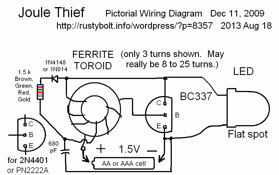
SJT-pictorialI received a request for a pictorial that shows the wiring of a Supercharged Joule Thief.  I redrew the one here to show the wiring of the SJT.

default

2013-08-17 Where and Where Not to buy LEDs

Paul discussed buying LEDs and I decided to write about some of my experiences with buying LEDs in this blog.

I bought some LED assortments from an eBay seller, I think he’s from Canada.  He’s still selling stuff.

Most of the LEDs had bubbles in them.  I dealt with him through email, and I  said that the LEDs were seconds or rejects, and he agreed to replace them.  His prices are not inexpensive but after dealing with him I can vouch for his honesty.

I bought LEDs from another eBay seller, and they also had bubbles in them.  I emailed the seller and the witch replied and told me that there was nothing wrong with the LEDs and if I filed a dispute complaint with eBay she would tell all the other sellers that they should not sell to me – to try to ban me.  Needless to say I filed a dispute, and I finally got my money back but I had to pay a few dollars for return postage and a tracking number.  I’ve never had to deal, before or since, with an eBay seller with such an argumentative and bad attitude.

So if you buy inexpensive LEDs you can expect some or all of them to have defects.  They may put out enough light to meet your needs, but they most likely won’t meet the specifications.  Common defects are bubbles, and mechanical errors that cause  the beam to be out of spec, such as the chip being off center in the clear epoxy lens.  One electrical defect is the wire lead is not bonded properly to the chip and may cause intermittent or dim light output.

But the biggest problem I’ve had with white LEDs was with the ones I bought from Hong Kong or China.  I did a lot of 24/7 tests for thousands of hours with white LEDs and wrote them up in my late watsonseblog,  After a few thousand hours, those LEDs put out a small fraction of their initial light output. to the point where four of those ‘used’ LEDs were much dimmer than a single identical new LED.  The only maker that I tested that had long lasting LEDs was Nichia.

For low power projects where the LEDs will be turned on for only a few hours a year, such as flashlights (torches), any white LED will last years.  For low power, where the LED will be putting out 20 percent or less of its maximum power, the same applies: any white LED will last a long time.

I looked at some of the LED packages to find out where I got them.  I purchased one package at SuperBright LEDs a few years ago, they’re still selling them and a lot more.  I purchased at least a few hundred from Nichia, when they were a dollar apiece.  These white LEDs survived 24/7 testing for more than a year, probably more than 10 thousand hours, and I would buy their LEDs for any LED lighting where long lifetime is important.

© RustyBolt.Info/wordpress
CyberChimps