From my late watsonseblog.blogspot.com, 2011-06-02
2011 Jun 02 Make A Joule Thief Pictorial
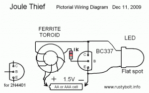
I’m attempting to make it simpler and easier to make a Joule Thief by using a pictorial diagram of a Joule Thief that’s, well, simple and clear. In order to keep it simple, I need the viewers’ input because what may look obvious to me may not be clear and simple to others. So, please leave a comment if there is something you don’t understand.
In this picture, the transistor has its flat face down, Emitter lead at the bottom, Base lead in the middle, connected to the resistor, and the Collector lead at the top. This is typical for American transistors. For European transistors such as the BC337, the flat face would be facing up. The LED’s cathode lead or flat spot is at the bottom, connected to the black wire and emitter lead. By the way, the black wire is held against the negative end of the battery by a button magnet.


Plz explain working of joule thefe.how to inductor going on and off
I’m not sure what you want explained. The transistor turns the current through the inductor on and off. The feedback winding keeps the circuit oscillating. The energy stored in the inductor causes the voltage across the transistor and LED to increase and when the voltage reaches the forward voltage of the LED, the LED conducts and it put out a pulse of light.
can you please send me schematics for joule thief,using pnp transistor 2n4403 and 1k resistor and how many turns for primary and secondary winding using a ferrite torroid with 14mm od and 11mm id and 5mm thick.im planning to use it in my salt water battery.tnx
You can see a schematic of both the NPN and PNP versions of a Joule Thief here.
http://www.instructables.com/file/FGOG8EQGI03BQVO/