default

2015-10-29 Joule Thief Brightness Measurements

It’s been awhile since I blogged this, so I may be saying what I’ve already said before.  But I get comments from others about how to make measurements of the LED brightness.  A recent one is in the comments of an older blog.  Many Joule Thief builders don’t have the minimum tools needed for some electronic projects.  But then Alessandro Volta, Michael Faraday, Georg Ohm and other pioneers of electricity did not have the tools and equipment we have today.  They had to invent equipment to make measurements.  It is surprising how a few simple things can be used to make measurements.

It is possible to make a good measurement of the light output of a LED using a grease spot on a piece of paper.  More about this grease spot comparison can be found here and in other websites, but instead of candles you use LEDs.

This website shows the experiment being done on a table in a room. But the room is dark when the experiment is done, so many people can see at the same time. It would be better to set up the experiment inside a cardboard box about 2 feet or 60 cm long and a width and height big enough to accommodate the experiment. Once the box is calibrated, the lid can be closed, and all that’s needed is a hole to see the grease spot.

The grease spot paper is mounted on a block of wood that has two upright posts to hold the paper. The block sits flat on the bottom of the box. The posts can be sticks of wood, twigs, coat hanger wires, anything that will not let the paper move. The grease spot paper is mounted on the posts with adhesive tape. During calibration this assembly will be moved back and forth between the LEDs that will be mounted on the ends of the box.

A hole has to be made in each end of the box so that the LED light hits the grease spot paper with the brightest point of the LED light beam at the grease spot. Both holes should be very close to the same point on each end. The LEDs should be mounted in the holes so that the brightest point in their light output hits the grease spot. Some LEDs have a beam that is not even, so several LEDs may have to be tried. The LEDs should be mounted securely so they do not move. Hot glue should do a good job. The wires to the LEDs should be mounted securely to the box so that there is no tension on the LEDs.

The LEDs are connected in series so that the same current passes through both LEDs. This causes the LEDs to have equal light output.

The grease spot box will need a source of current for the LEDs. A simple source of 5 VDC is a phone charger. With a resistor in series with the 5 volts, and a white LED that has a voltage drop of 3.3 volts, that leaves 1.7 volts across the resistor. The current should be 20 milliamps or .02 amp. 1.7 divided by .02 is 85 ohms. A close common value is 82 ohms. If this is not obtainable, then a 100 ohm resistor will give 17 milliamps. A 560 ohm resistor in parallel with the 100 ohm resistor will give 20 mA.

But first we want to calibrate the grease spot. Both of the LEDs are connected in series and a 100 ohm resistor is connected in series with the LEDs. The remaining two ends of the wire are connected to a 9 volt battery. A power supply can be used too. This is only used during calibration and won’t be needed afterwards.

The light in the room should be low. If not then put a blanket over your head and the box. With the LEDs lit, the grease spot is moved back and forth between the LEDs until the grease spot looks the same as the paper around it – it seems to disappear.

This point should be marked where the wood block is on the box. The block should be about in the middle of the box. The block should be secured with some strong tape. The block should not have to be moved again. From now on, the grease spot can be seen through a hole or slit in the box.

The 9V battery is removed and the LEDs are disconnected. One LED is connected in series with the 82 ohm or 100 ohm resistor. The remaining ends may be connected to the 5VDC charger, and it will put 20 or 17 milliamps through the LED. But we really want to vary the current, from 20 mA down to just 1 or 2 mA. So we add a variable resistor or potentiometer between the 82 ohm resistor and the 5 volts. This pot will have a resistance of 1000 ohms or less, but not lower than 470 ohms. It will allow adjusting the current down to 2 mA for a 1000 ohm pot.

The remaining LED is connected to the Joule Thief. With the JT powering the LED, the other LED’s pot should be adjusted until the grease spot disappears. We know from the calibration that at this point both LEDs were the same brightness, and they had the same current passing through. So we can now measure the voltage across the 82 or 100 ohm resistor and calculate the current by dividing the measured voltage by the resistance. We measure 1.23 volts DC across the 82 ohm resistor. So 1.23 volts divided by 82 ohms gives .015 or 15 milliamps. Thus the JT is putting out the equivalent of 15 milliamps.

default

2015-10-26 Flashlights Fenix E01, LD01, LD02, ITP EOS A3

This blog continues at 2015-11-18…

I just finished looking online at Fenix LD01 and E01 flashlights (torches).  I was shocked when I found the prices of the LD01 have skyrocketed to $42.  I looked at the LD02 and found it also uses a single AA cell, but it has a push on, push off switch in the end cap.  The price is much lower than the LD01.  I think what may have happened is the LD02 has replaced the LD01 which is no longer made.  Sellers may be taking advantage of the supply no longer meeting buyers demands.  So if I decide to get the three brightness keychain light, I may get the LD02.

I looked for the cheapest Fenix E01 flashlights, and found some for $11.00.  They make great inexpensive gifts.  They are a single brightness keychain: light, small and sturdy like the other Fenix lights. The one big disadvantage is the light has a single brightness which drains the AAA cell rapidly, in less than an hour. The way to mitigate this problem is to buy several rechargeable NiMH cells and have one cell in the light, one cell in my pocket ‘just in case,’ and two spares in the charger, fully charged.

Since I’m not working ‘full time’, I haven’t been using my keyring flashlight as often. I have found that if I use regular NiMH rechargeables the cells need to be recharged after a month or so of not being used. This is because they self discharge, about 30% a month, which is normal. I found that I can buy the Eneloop rechargeables which have a very low self discharge rate, less than 30 % per year. So I have been buying The Panasonic Eneloop cells. The Eneloops were originally from Sanyo, but they sold to Panasonic, so Sanyo Eneloop is older stock. Either way, they are not cheap. But I think they are worth it.

Back to the lights. I found some low priced ITP A3 EOS flashlights, but it didn’t say how much the shipping was. I had to add them to my cart to find out. I was shocked! The shipping was too high, something like 6 dollars each, with no discount for buying more than one. I found out the hard way when I did the 1 click buy on Amazon, and got hit with a high shipping charge. Now I always add it to my cart and check the shipping when I checkout. So I deleted those and bought some others instead, and got free shipping.

I also looked at the ITP EOS A3, which is about the same as LD01.  They are a bit smaller and lighter.  They come in different colors. I bought some of those, too. Olight was the original seller, now ITP sells them. But I find that I can sometimes find the older Olights for cheaper than the newer ITPs. I like these lights: they are shorter and lighter than the Fenix LD01, but are still well made. They also have three brightness levels. The ITP lights now come in Max version, which is brighter and has a fourth mode, a strobe or flash mode. I don’t really see a need for this. If you want to get a flash effect, just point the light at someone and wave it back and forth, and they will see the light go on and off. The added brightness is nice, as long as it doesn’t take more from the cell, which already has too short a life. Some of the lights come with a high, medium, and a ‘moonlight’ or ‘firefly’ mode which is lower than low brightness. I would rather have the low mode, which is more useful to me than those other lower than low modes.

I have also found that twist on, untwist off lights are easy to switch modes, but the pushbutton lights can be harder to control. And if the pushbutton is on the end cap, the light most likely will not sit on its end, if you want to use it as a candlelight. Still, some people like the pushbutton on the end, and don’t like the twist lights. The twist lights are more reliable; I have had the pushbutton switches fail occasionally. There’s nothing much to go bad on the twist light. The O-ring may get worn, which may lower the waterproofing. But that doesn’t affect the switch, as long as the light stays dry.

I’ll end this by saying that there is no such thing as a perfect flashlight. Every flashlight is a series of compromises between light output, battery capacity/operating time, cost, and other factors such as size, waterproofing, durability, etc. The one single major flashlight improvement over the past decade has been the white LED. It alone has given flashlights a whole new life and meaning. They have gotten smaller, brighter, more durable, and less expensive over the years. Let’s hope they continue to improve. 🙂

Update Oct 27 – I looked at some of the single cell flashlights Dealextreme.com offers. I ordered one that looks very similar to the Fenix LD01. I also ordered several of the under $5.00 flashlights they have. Then I saw something very interesting.

They sell a flashlight head for $10 that screws onto an e-cigarette battery. This is a real beast! It puts out 800 lumens, which is ten times what the keychain lights put out. For just ten bucks! I looked for e-cigarette batteries but they don’t have any, which strikes me as odd. I searched online and on eBay I found a few lithium-ion rechargeables that can handle the heavy 2.8 amp load, and they were in the $35 to $45 range. I could order 1 or 2 of these flashlight heads, and wait for a month until they arrive from China (DXsoul ships from the US but doesn’t offer them). Then when the heads arrive, I could buy the battery pack online or look for one in the e-cig store (probably cheaper online). Right now, near the end of October, the shipping slows down as everyone starts ordering stuff from China to stock up on items for the end of the year black Friday and Xmas holidays.
This blog continues at 2015-11-18…

default

2015-10-22 Brother MFC-L2700DW All In One

Earlier this year I bought a Brother MFC-2700DW all-in-one printer/copier/scanner/fax from Staples for $170.  My plan was the scan in the many photographs that my family took in the previous century.  I didn’t know at that time that my sister had thousands of pictures more of her family that she wanted digitized.  And I didn’t know I would be spending months and hundreds of dollars in the process.

I had a small, cheap Samsung b/w laser printer that I gave to my sister.  I put the much bigger Brother MFC in its place in my computer desk.  It wasn’t easily accessible so I took it and a cheap Dell Core i3 laptop down to my sis’ place and set them up on her dining room table.  That was four months ago, and three thousand pictures later I still have at least thousand left to scan.

I started out with black and whites, some almost a hundred years old.  Lately I  have been scanning mostly color photos, some old enough to be faded in one or more colors, so I have to spend more time adjusting the color balance.  I have been using Irfanview, which despite it being free, does a decent job with the scans.  I have been spending 2 to 4 days a week mostly scanning, staying overnight most of the time.

Sometime in the last few weeks, with over 2000 scans completed, I have been noticing that occasionally some photos with normal color have been scanned in with a purplish color offset over the whole photo.  At first I corrected for the offset.  Then I had to correct several photos in a row, so I opened the top cover while it was scanning and I noticed that the scanner bar’s lamp had a purplish color.  No wonder the photo had the magenta offset!

I noticed that it was okay when I first started scanning or if it had been several minutes since the last scan.  When I first started correcting, I found it took several minutes, which gave the lamp a rest and slowed my scanning down a lot (too much!).  I saved the corrections in the setup file so I could load the needed one in when I needed it.  This helped speed scanning up, but then the lamp was not getting a rest and the magenta offset got worse.  The photos didn’t look right after the corrections.  I thought that the scanner lamp was ‘used up’, so I took a break and searched online for a lamp to replace it.

A few companies had scanner lamps, but were not specific about which lamp was needed for my scanner, and I couldn’t find any prices for them.  So I looked for a new Brother all-in-one.
Last weekend I found I could buy (almost) the same Brother, model MFC-L2700DW, from Staples.com website for $150, cheaper than what I paid for the original. By the time I got to the store Monday, the price had gone up to $200! I talked to the salesdroid about that, and he said ‘we will price match for any of the big retailers, including Amazon.’ So I checked Amazon and they were selling the MFCL-2700DW for $110! He took one up to the checkout and price matched Amazon, and I walked out of the store with the new Brother for $118 and change, including sales tax, and I saved $90!

So now I’m back in business scanning with a new MFCL-2700DW. I had to reload some drivers which were on the included CD. I noticed that on the first few scans there was some purplish color offset, but that went away and hasn’t returned. I am going to search and find if this problem is an issue for Brother scanners, other brands, or if it is just a lifetime limit on scanner lamps in general.

I am over 2800 actual scans, and over 3000 if I count all the rescans and goofs I have had to redo. I hope I get done without any issues with the new scanner in the Brother MFCL-2700DW all-in-one. It has been a huge amount of work, but the reward will be that I can give anyone in the family a DVD with all of the photos on it, and they will be able to browse it and see any of the family photos. They can also load all of the photos onto their hard disk and set their screensaver to display a slide show of all of the photos. That is what I am doing right now with the laptop.

Update – I took the printer over to an authorized Brother printer repair company, and talked to the guy. He said out of warranty repair would be about $130.00, which is more than I paid for it. But it has a 1 year warranty, and I showed him the receipt, and he said I could get it fixed under warranty. But it will take more than a week to get the parts shipped and just a half hour to do the replacement. I said I could live with that, so I guess he will have it fixed next week. I’m glad I kept the receipt.

default

2015-10-12 Too Many Ferrite Beads

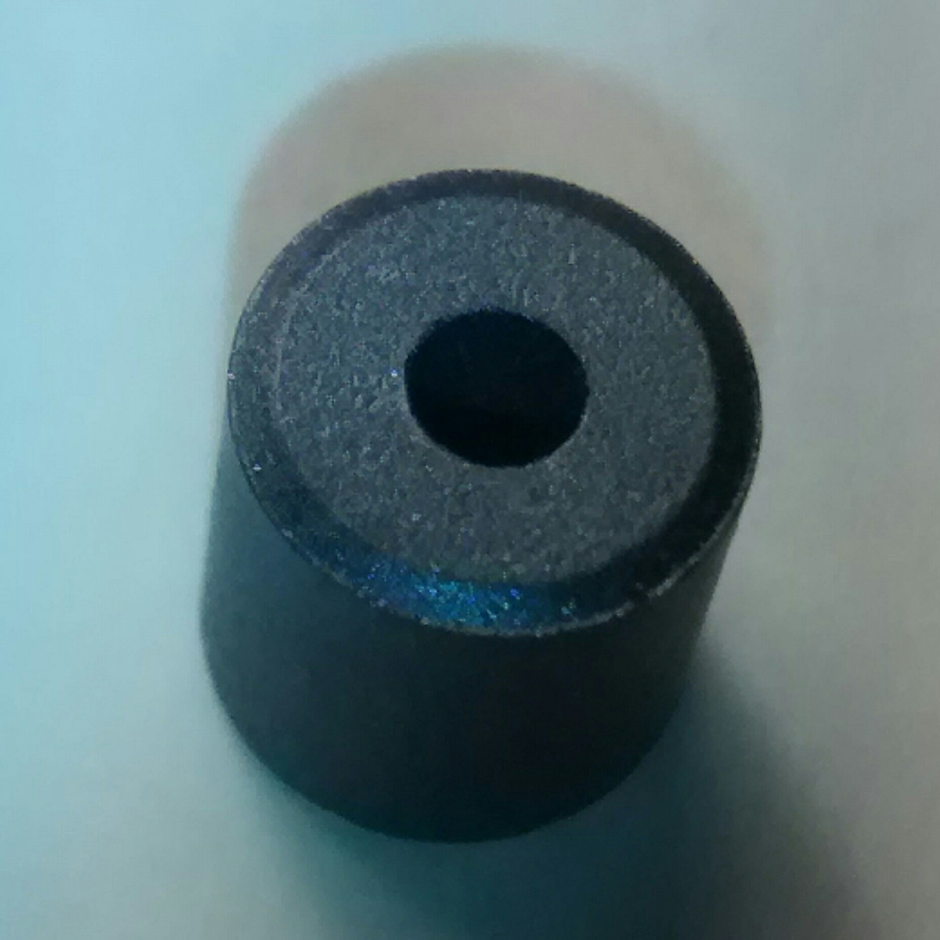
Well, I’m going to receive a package from Electronic Goldmine with a bag of 800 ferrite beads.  They’re made by Fair-Rite, type 2643000801, which is type 43 ferrite material.  This is a medium mu material, for frequencies in the 100 to 300 MHz range. But type 43 works okay for JTs as long as there are a few more turns; enough to have about 100 uH inductance.
image

I’m going to try making a Joule Thief (JT) with a coil made with one of these beads.  I’m not sure if I can wind enough turns on this small bead to make a decent JT.  I’m hoping the coil will have a few tens of microhenrys of inductance.  I may have to use two beads together (see below).  Whatever the case I will have a lot of fun experimenting.

If this doesn’t work good, I will have over 700 ferrite beads to give away or sell.  Or put one on every wire to or from a PC board to cut down on radio frequency interference.

Another experiment I did quite a while ago was to connect two small ferrite toroids together with a link loop. A single toroid didn’t have enough room in the middle for the number of turns I needed. I threaded a single length of wire through two toroid cores and connected the ends together. This linked both cores together electromagnetically; whatever was in one core was tightly coupled to the other core. This could work for these ferrite beads. The small hole has to still have enough room for the turns of wire for each of two windings. That means fine wire.

Another one of my experiments comes to mind. One time I had some toroid cores that were not high mu. To increase the inductance, I stacked two cores, one on top of the other. Each winding was wound through both cores. I have so many beads that I could stack 3, 4 or even more to give more inductance, as long as I can get the wires through all of the cores. One thing I found out about Fair-rite cores is that the last digit tells if the core has been polished to remove sharp edges. If it’s 1, that means it is not polished; if it’s 2 then the core has been polished and there should be no rough edges. These beads are unpolished so they may have sharp edges that could damage the wires. I will have to use a deburrer to smooth the edges of the holes.

I bought a few other items along with the beads. I think these should keep me entertained for awhile.

Update Oct 16 – The beads and other parts arrived. The box of beads is quite heavy, as should be expected of something made of glass and metal.

I wound 8 turns of 30 AWG magnet wire through the center hole with room to spare. The length of the wire was 8-1/2 inches, the same as the width of a sheet of letter size paper. The inductance measured 98 microhenrys, which is just right for a JT. I have to get 8 turns of 3 lengths of 30 AWG wire in the hole. What i’m concerned about is the very sharp edges where the wire enters and leaves the hole. I tried two lengths of 28 AWG and one length of 32 AWG enameled wire, each 8.5 inches long. I could barely get 7 turns on the bead, but some of the enamel got scraped off by the sharp edges. Even so, the windings measured 102 uH, which is great. I think it should hold three lengths of 30 AWG, all 8 turns.

Update Oct 21 – I thought it would be best if I got rid of the sharp edges around the hole. I tried sandpaper by cutting a small strip and rolling it into a spiral that fit into the hole. It took off a small amount of the sharpness, but I think it would take too long to do, and the sandpaper got dulled quickly. I think I will try a diamond sanding block to see if it’s better and faster.

I’m not having much success with the diamond sanding block. The little bumps don’t want to go into the holes.

Update Oct 25 – I was in a store with a crafts dept, and was looking at some tools. I saw a tool called a bead reamer. It looks just like a round file with a sharp point, but instead of fine grooves, it was smooth and covered with what looked like diamond particles. The package said nothing about diamonds or what the material was. But I knew that beads are made of glass, so it had to be something that could grind glass.

I bought one and tried it on one of the ferrite beads (it was less than 4 dollars US). My fingers turned brown as the reamer took off the sharp edges of both the hole and the outside ends. It worked good, my only complaint is that I have to do the work by hand.

It will do the job for a few beads, but I don’t want to spend a lot of time doing this. I saw a project online on how to build a ball mill out of some wood, a length of 4 inch ID ABS pipe, rubber end caps, three ball bearings, and a small DC motor with a gear head that turns ten or so RPM. I could put a handful of beads into the container and let it run for several hours or longer, until the edges of the beads smooth out. But I’m not sure this will do anything to the sharp edges of the holes.

I found some diamond bead reamers on eBay, and I ordered a few of them. One of the bits looks like a cone, which should make it easier to take the sharp edge off the hole. They will be shipped from China, so it could take several weeks to get here.

Update Nov 12 – I received the diamond coated reamers today and they work okay for taking the sharp edges off the beads. But it may take a few minutes to do a single bead, so it will take me a very long time to do a hundred or more.

default

2015-09-28 Spaniards And Native Americans

I have been thinking about how today’s historians have influenced peoples’ thoughts about past historical events.  I would like to say what my opinion is about this historical revisions. This might be called pseudohistory, which, according to this link:
“Writers Michael Shermer and Alex Grobman see pseudohistory as “the rewriting of the past for present personal or political purposes.””

In 1992 the U.S.A was preparing to celebrate the 500th anniversary of Columbus discovering America in October.  Decades before then history had treated Columbus as a hero.  But before 1992 Columbus had been changed to a villain who had brought European diseases to America, which killed many native Americans, who had no resistance to these diseases.  White man brought alcoholic drinks, which the Injuns abused. The white man’s ways were forced upon the ‘Injuns’, and when they fought back, white men branded them as savages.  Columbus was blamed for starting this, even though he was an explorer, not a settler.

As a result of the backlash against Columbus, the 500th celebration was subdued.  Someone once said, ‘Columbus didn’t know where he was going, he didn’t know where he was when he got there, and he did it all on borrowed money.’

Here is another article about St. Serra.

The author said in this article that in California “the missions were coercive religious forced labor camps.”

Religious? Obviously.
Camps? Were all of the natives living in a camp? Inside of the Mission? With guards around to prevent them from escaping to ‘freedom’? I’m not sure all of those were true.

My thought is that is that instead of living a subsistence life at the whim of mother nature, with feasts or famines depending on the weather, the natives could live an organized life with some planning, to get them through the famine years. Was this what kept them from escaping? Possibly.

Coercive? Were they forced to learn to practice the Church’s religion? It came with the missions.

What other things were the natives coerced into doing? Forced labor? Well, they had to contribute to the productivity of the Mission; if you don’t, you and others will end up starving to death (at that time, there were no other sources of food). The Mission was like a commune, where everyone had to contribute. The zanjero was a very important person, for without water, you couldn’t grow your food.

The natives were coerced by the mission into learning the Spanish language. Were they coerced into not using their native language? I don’t know. I do know that in order to teach natives how to farm, the missionaries had to talk to the natives and the natives had to understand what the missionaries said.

A lot can be read from those few words ‘coercive religious forced labor camps.’ I am certain that before the missions, the natives had to live on the land, enduring hardships, drought, famine, disease. I am not certain that living in a mission was worse than living on the land.

A friend, Ted, commented this on FB (used with his permission).

default

2015-09-18 Hand Cranked Flashlight

I’ve been getting close to finding a  motor to use as a generator for a hand cranked flashlight.  I found one a few months ago, which even included a crank. But the crank was small and hard on the fingers.

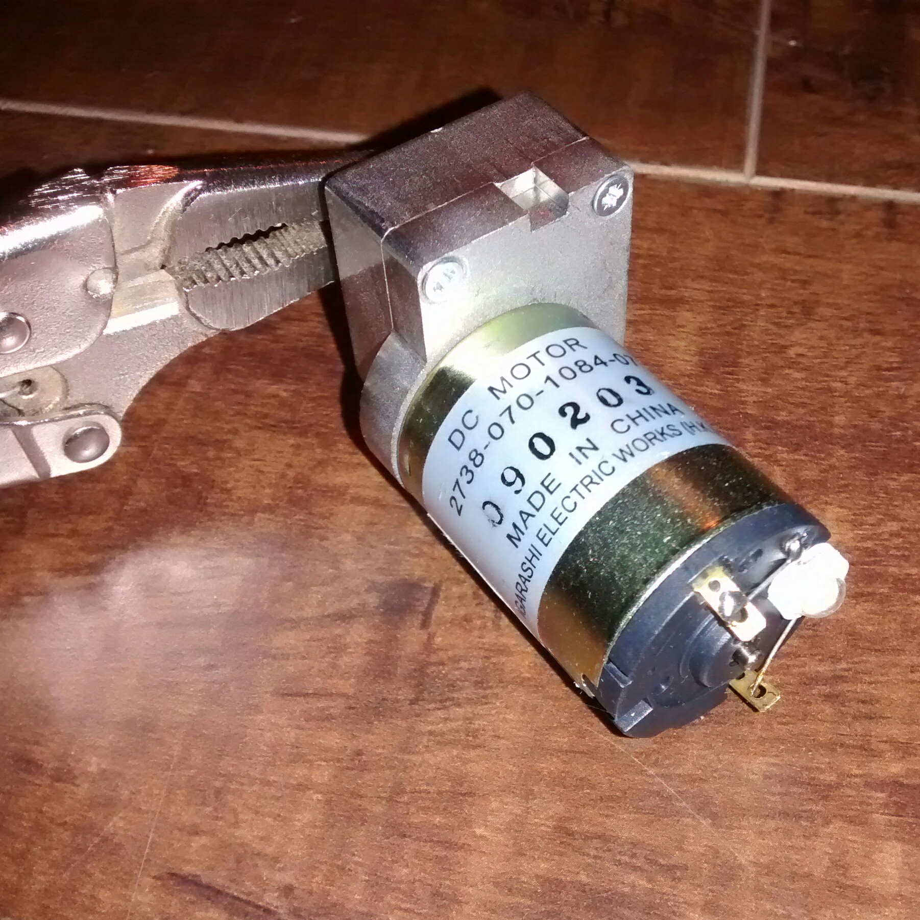
This one from Electronic Goldmine (apparently they’re sold out) has a motor and gearbox, with a shaft for a crank.  The shaft has a flat for mounting a crank with a setscrew (see photo).
image

I don’t have such a crank so I used a mini vise grip for a makeshift crank.  With the 1 watt white LED connected to the two contacts (white disk with wires), I can crank at a reasonable speed and get a nice amount of light output.  The LED gets barely warm, which means to me that it’s not getting a full watt of power from the generator.  But it’s enough to light the LED and use as a flashlight.  A better and lighter crank might help to increase the output.

I checked Goldmine website and couldn’t find any of the ones I bought. The gearbox makes it much easier to crank. But a small wheel from a caster might be used. The motor can be mounted so the shaft is pressed against the wheel and driven by friction. The wheel is then spun manually. The size of the wheel determines how easy it is to spin. It helps if the shaft has splines or is not smooth, so it doesn’t slip when the wheel turns.

I have also had some success with rubbing the shaft on a rubber or non-slip surface. The best example of this is a bicycle light dynamo. A dynamo (or stepping motor) will generate AC, which has to be rectified to make DC. But it can be driven in either direction. So a back and forth motion on a soft surface will drive a LED, if a 1000 if or more filter capacitor is across the LED, and rectifier or full wave bridge rectifier is used.

Another way of generating AC is to use the head positioning stepper motor from a CD drive. These have a shaft with a spiral groove in it. They will light a LED when the shaft is spun by rubbing on a bike tire or other similar surface. It’s not difficult to light a LED brightly with any small motor.

I have also had good results using a stepper motor from an ink jet printer. These drive the print head and sheet feeder. Stepper motors from other devices such as CD drives work, too. I found a YouTube video where a guy gets 10 plus watts from his hand crank generator with a stepper motor, rectifier, filter capacitor and control box. This is used to charge a cell phone. He has to crank it fast to get the full 11 watts, so a more realistic and easily done output would be 5 to 6 watts at 5 volts, which is about what a cell phone charger puts out.

One problem with these chargers is they require you to hold them with both hands and crank continually for a long time. The generator should be mounted (or mountable with a clamp) to a stable object (like the edge of a table or workbench) so that it can be cranked with one hand and leave the other hand free to do other things. A good way of mounting odd shapes is to use a hose clamp. These could be small or as big as a radiator hose clamp.

default

2015-09-01 Other Relay At Electronic Goldmine

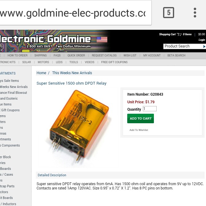
I also got several of these relays from goldmine-elec.com.  I got them when they were on sale. There are more characters printed on the coil, including the 1500 ohm resistance.

These are standard frame relays, with double pole, double throw contacts (see the pic). The pins are made for insertion into a PC board.  The coil is 1500 ohms, and 9 to 12 VDC will operate the contacts.  The contacts are rated for 1 amp at 120 VAC.  The contacts look heavy duty, so it might be able to handle more.

image

I connected 12VDC to the coil and it pulled in with a click. With 12 VDC across 1500 ohms, that’s 12/1500 amp coil current, or 8.0 mA. And 8 mA multiplied by 12V is 96 milliwatts. That’s low enough for a Joule Thief with a rectifier and filter capacitor on the output to drive the coil. Then just about any low voltage could pull in the relay. There are other circuits that would benefit from this sensitive relay. With such low current, any transistor can drive the coil. And the relay provides excellent isolation between the contacts and coil, while drawing a minimum of current from the power supply. A typical frame relay draws several times this power.

I had many boards from an old PBX system that used 48 volt relays to connect the phone line when it was in use. These are small relays, taller but not much bigger than a 15 pin DIP IC. They are made by Omron or .

These have a coil resistance of either 5500 or 9000 ohms. The 5500 ohm coil draws 48/5500 amps, or 418 milliwatts when activated. That’s 4 times as much power as the relays from Goldmine.

default

2015-08-25 Reed Relays At Electronic Goldmine

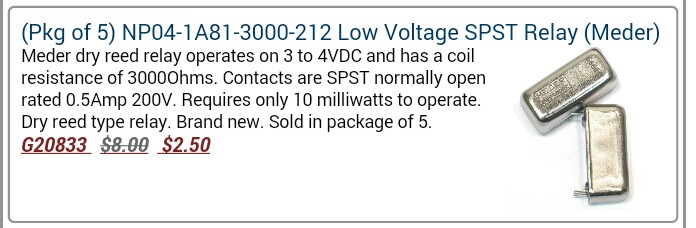
I was interested on the New surplus relays that goldmine-elec.com has recently acquired. BTW, these may be sold out and no longer available soon. 
image

I noticed that the operating power is only 10 to 13 milliwatts, which is extremely low. But the figures don’t make sense. Ten milliamps would go through 300 ohms, not 3000 ohms. I’ll have to check the resistance when I get them.

I thought that this might be lower than the amount of power dissipated by a forward biased diode when current is passing through it. Say, for instance I had a solar panel outside and I have to use a diode in series, a 1N5817, for instance to prevent current from flowing back into the panel at night. Say the panel puts out 1/2 amp (contacts rated maximum). A half volt drop across the diode at 1/2 amp is 1/4 watt or 250 milliwatts. In this case, the relay would save save over 200 milliwatts. The relay has to turn on and off only once a day, so its lifetime would be very long. The speed makes no difference. This seems to be a good use for them.

I also thought the relay would work well on the output of a low power Joule Thief. I could put a 1N4148 diode and a 10 uF filter capacitor on the JT output to turn the output into DC. The relay could then be operated by a voltage less than 1 volt DC. A red LED might be put in series to indicate when it is on. The relay could be rewound with less turns of wire, but this wire is so fine that it would be difficult and tedious to do it, not to mention that the relay is in a sealed metal package.

This relay can be used, along with a snubber diode, on the output of a microcontroller. It will give very good isolation between the microcontroller and the external circuit it is controlling. Transistors are typically used for this. But if the transistor fails, the high power could damage the microcontroller. But remember, the electromechanical relay is much slower than the transistor.

I’ve thought of other uses for this low power reed relay. I have to emphasize low power, because most relays take a lot more power than this to operate, and can be used in higher power circuits. But lower power relays are uncommon and useful for low power circuits.

default

2015-08-26 Atomic America Book About Nuclear Power

I finished reading this book about Admiral Hyman Rickover, father of naval nuclear propulsion, and about the deadly reactor accident that took the lives of the only three people to die this way in the U.S. The author is Todd Tucker.

Up until reading this book I had read only anecdotally about the nuclear accident at the facility near Idaho Falls, Idaho, on Jan 3, 1961.  This book goes into occasionally gruesome details to explain what most likely happened, contrary to the often claimed murder/suicide.

A large part of this book is devoted to Adm. Hyman Rickover, and his criticisms of just about everything, including nuclear power.  He managed to get the U.S. Navy submarine fleet under nuclear power.  Despite his shortcomings and habit of irritating people, he truly was an amazing man.

I recommend Atomic America as a history and biography of events and people in nuclear power.

Another book I finished recently is The Great Transition by L. Brown, et. al. It is about the transition from fossil fuels to renewable fuels like solar and wind. This isn’t the first book of his that I’ve read. In all fairness I have to say this book is one-sided. They talk about the advantages of renewables, but fail to mention their drawbacks. They discuss nuclear power, and I’m afraid it doesn’t sound optimistic. They point out the long construction times, excessive cost overruns, and unpopularity of nuclear power. Environmentalists, NIMBYs, and spent fuel disposal issues, too. It doesn’t look like nuclear power has a future.

default

2015-08-15 Parts Used For Electronic Circuits

I get emails from Electronic Goldmine concerning their latest sales items.  I have noticed a lot of electronic parts of a certain category in their sales.

They may have a large number of parts from manufacturers that are switching over to newer technologies.  I have noticed a large number of relays in their sales, specialty relays such as ones used for switching power in AC powered equipment, or for controlling high currents in a 12 volt auto system.  Then there are reed relays, where very small currents are switched.  Most of all these relays are old style, with through hole for mounting to a circuit board, or with pins to plug into a socket.    My assumption is that these relays are being replaced by whole modules which have all functions in a single replaceable module, such as car lighting or accessories.  Or through hole parts are being replaced by surface mount parts. Another relay replacement is the SSR or solid state relay. The SSR’s input is isolated from the ‘contacts’ typically by an optoisolator.

One part they’ve had a lot of recently is power MOSFETs.  These are through hole, most likely replaced by a surface mounted part.  The MOSFET can be used like a relay. The prices can be very cheap when on sale.

Standard relays have the advantage of complete electrical isolation between the coil and the contacts, because the actuation is done electromagnetically. But the disadvantage is they are slow, taking milliseconds to actuate. Another disadvantage is the standard relay requires power to hold the contacts in the actuated position (there are latching relays that avoid this). This power can be substantial, tens to hundreds of milliwatts, which can be more than the power of the controlling circuit. So eliminating the relay can save power and increase efficiency. In contrast, a MOSFET’s gate draws no power when the MOSFET is on or off. It only takes some current to charge or discharge the gate capacitance when switching from one state to the other. That is less power than a standard relay.

As I’ve said before, many if not most of the through hole parts will continue to be available from suppliers, but not at the low prices you can find at surplus electronics companies. That’s one reason I try to get them in quantities to last awhile.

© RustyBolt.Info/wordpress
CyberChimps