default

2015-08-08 Recycle Plastic Bags

I came across this at a website with other projects.  Just scroll down to Recycle Plastic.

The basic idea is to build up sheets with an iron.  The raw ingredient is dozens of plastic shopping bags.  My only concern is that using the iron might be more costly on your electricity bill than if you went to a hardware store and bought a sheet of plastic.  But I think it’s a novel idea and might lead to other things such as sealing things inside a plastic envelope to make them waterproof.

One thought comes to my mind.  The plastic sheets are translucent, depending on color and thickness.  These could be used as diffusers to spread out the light from point sources such as LEDs.

There are other projects on this webpage that you might find interesting.

default

2015-07-21 GE Bright Stik LED Light Bulb

I went to Home Depot this weekend to buy some stuff to fix the leaky toilet, and I walked past the display for the new GE Bright Stik LED light bulbs.  I was attracted to their shape and small size. They come packaged 3 to a box, and there were two types: bright white and soft white.  These Bright Stik lights have a frosted glass cover that is about the size and shape of a plastic prescription pill bottle. They are much smaller than the usual LED lights, which resemble the incandescent light globes. 

These GE Bright Stik lights are rated at 760 lumens, a bit less than a 60 watt incandescent light, which is 840 lm. They draw 10 watts from the power line. So I guess that they put out 76 lumens per watt, which is not all that efficient.

The package says made in China. The shape and small diameter make this light a good choice for appliances and fixtures that use a long, thin tubular light bulb.

For some odd reason, the bright whites were $10.97 and the soft whites were $9.97.  So I bought a box of the soft whites.

I tried one in a three light ceiling fan fixture and it looks about the same as the other two 60 watt equivalent LED lights in the fixture. Each light is inside a glass flower, so the Bright Stik light’s odd shape isn’t so noticeable. After being on for awhile it got noticeably warm, but that is normal for a light this small.

The price of $3.33 per light is a new low for me. Just a year or two ago the cheapest LED light was $20.00, so the price has come down to 1/6 of that. The lifetime rating is half of the usual hours but it’s still cheaper to have two go bad than one of the typical LED lamps. And only time will tell if the LED lights will meet the 22.8 year lifetimes claimed by most LED lights now made.

default

2015-07-18 Smone 4 Ring Earphone Jacks

I was Reading about a guitar fx dongle that plugs into a Smone earphone jack. For a Samsung smone it has to have the capability called ??. This recognizes the device when it’s plugged in. Since the device must have power, apparently the earphone jack has to analyze the device when it’s plugged in to determine if it’s a passive device such as an earphone or if it needs power, such as the dongle.

I have been noticing this phenomenon lately. I plug an earphone into a smone (smartphone) or laptop, and I see a bubble pop up on the screen saying I plugged something in. With Windows 8.1, it asks me if it’s an earphone, among other choices. With the smone, it may not acknowledge, but if an app requires an earphone, it will ask for it to be plugged in, and knows when it is plugged in. The FM radio is one example of this.

Another thing that had a problem was when I tried to record from my Samsung Galaxy 4S earphone jack by plugging a digital voice recorder into it. The G4S would not recognize the voice recorder and kept playing through the speaker. I had to use a ‘Y’ splitter for two headphones, and plug a headphone in one jack along with the recorder in the other jack. Then it switched over to the jack. The conclusion is that if the plugged in device does not have low impedance, like an earphone, then the Galaxy 4S will not switch from the speaker to the earphone.

The earphones that come with most smones have four metal contacts on the plug, instead of three like the stereo headsets. The fourth typically goes to the microphone that is a blob in one of the earphone leads. It’s for hands free telephone calls. There are two sizes of jacks/plugs; the standard 3.5 mm or 1/8 inch plug/jack, or the smaller 2.5 mm jack. Both have the 4 contacts. It seems that most smones have standardized on the 3.5 mm jack, while the cheap flip phones and similar use the 2.5 mm jack. Both sizes have been used for many decades, with 3 (stereo) or 2 (mono) conductors.

default

2015-07-13 The Fenn Treasure

The Fenn Treasure is a treasure reportedly worth $1m–$3m hidden by art dealer and writer Forrest Fenn in the Rocky Mountains.  According to Fenn, many people have claimed to have found the treasure, but no one has provided any evidence to him supporting their claim.  As of 2015, Fenn has stated that to his knowledge it is still not found.

This article was seen on CBS Sunday Morning, Jul 12, 2015.  I had heard that someone had hidden a treasure somewhere, which many were very reluctant to talk about, obviously because others would then try to beat them to it.  I didn’t (and still don’t) think much about it, for reasons I may state later.  But given that the Rocky Mountains are so large, it seems very unlikely that some independent treasure hunter, even with help, would be able to find it in a reasonable length of time.  It did say that he had periodically given hints about where it is, but a hint can be very vague and abstract.

I have looked at this from Fenn’s point of view, and I had some thoughts about how I would go about it.  In the last year or so there was another person who hid money in several places and gave hints to the money’s whereabouts online.  The news media had videos of hordes of people showing up at a beach and finding money hidden in the sand.  The individual may have done this to get media attention.  Or perhaps someone wanted to create a flash mob.

The same motives may be had by Fenn.   So his much more valuable treasure may be hidden much better. 

I also thought that if I was Fenn, I would not hide the whole treasure, I would hide a small part of it, along with a note telling the finder to contact me for the rest of the treasure. That way, the finder would not be able to disappear with no one knowing that he had found the treasure.

This would also make it much easier to hide the treasure, since the treasure’s size could be as small as a single coin, along with my contact information and instructions.  This could be in a small plastic bag, small enough to fit in the palm of my hand.  It could be hidden in a hole bored into a tree.  I would not have to carry this ‘treasure chest’ around, and risk having someone see me concealing it.  A treasure chest would have a much greater chance of being damaged by the elements, scavengers and insects.

But what if the finder decided to keep just what he had found, and not contact me?  I suppose that that person could be satisfied with what he found, and not contact me. But if he had read the included note and knew how much more the treasure was worth, he would most likely contact me to collect the bulk of the treasure. It could be that Fenn his it so well that it may never be discovered. Or Mother Nature played a dirty trick on Fenn and moved, AKA rehid the treasure so not even Fenn knows where it is. Only time will tell.

default

2015-07-08 KPC AKA Key Product Characteristics

This is about electronics components, despite this off-topic intro. Last night I watched a Frontline episode on PBS about the drug resistant superbugs that are resistant to antibiotics.  They talked about one of the genes that causes this drug resistance; it produces an enzyme called klebsiella pneumoniae carbapenemase or KPC.

I searched for KPC online and Wikipedia had it, so I clicked on it. It turned out that many things are abbreviated KPC and one of these is key product characteristics. This immediately brought to my mind the data sheets used by electronics manufacturers, especially semiconductors. Wikipedia does not have a wiki about this, or key product characteristics in general, and it asked if I wanted to create one. But I don’t believe I’m qualified to write about it in general. So I decided to write a blog about KPC as I think they should apply to semiconductor specifications, especially transistors.

Historical Background
The early days of transistors were fraught with problems that caused transistors to quit working properly and die. As with any new product, the early manufacturing was expensive. The devices were assembled and tested manually and were expensive before mass production was introduced. Most of the early purchases were made by the government, mainly military and NASA, for satellites and spacecraft. Reliability was of utmost importance, since these projects cost many millions of dollars. One component failure could terminate the whole mission. So early on every component had to be tested to meet the specifications given by the gov’t agency. The industry adopted uniform specifications so that components made by various manufacturers could be assured of compatibility. The “spec’s” were given in a datasheet.

Transistors
Semiconductors such as transistors are very small and can be damaged by excessive heat. Early germanium transistors were encapsulated in a plastic package, but much of the problem was that the package allowed air and moisture to get into the transistor chip, causing it to fail. So the packages were changed to a sealed metal can, hermetically sealed by welding. This greatly improved reliability.

Datasheet
The datasheet begins with the manufacturer’s name and product name, such as 2N4401. A single specification may have 1 or a few lines starting with the name of the specification and conditions, the abbreviation of the spec, a minimum and if applicable, a maximum value, and sometimes a typical value. The last spec is usually the measurement unit, such as volts or milliamps. The current gain is dimensionless.

Power
The first page of the transistor’s datasheet gives the specs for the power dissipation, or Pd. This depends on the size of the chip and package and if it is mounted on a heat sink. For small signal transistors this is usually below 1 watt, typically 625 milliwatts. For power transistors this is from a few watts to several tens of watts for a plastic TO-220 package. For the 2N3055, in the metal ‘diamond’ TO-3 package, it is 115 watts. But the power is limited by the heat sink, which must be able to dissipate that much power without getting excessively hot.

Maximum Collector Voltage
The maximum voltage from collector to emitter, with the base not connected, or Vceo, is the highest voltage that should be applied to the transistor’s collector. Any higher, and the transistor could break down and start conducting current, which could damage the transistor. The Vceo may be less than the other Vce or Vcb voltages.

Current Gain, Beta, hFE
An important specification is the current gain, AKA beta or hFE. The collector’s current is the base current multiplied by this number. Say the base current is 1/2 milliamp and the transistor’s current gain is 200. The collector current will then be 100 milliamps. The hFE depends on the current, the voltage and the temperature, among other things. These variables are given in graphs in the datasheet.

High Frequency Performance
This is usually given by the frequency at which the current gain drops to unity. It is abbreviated fT. A typical value for silicon small signal transistors is 200 MHz.

Vce(sat)
The Vce(sat) is the voltage from collector to emitter with the transistor forced into saturation. This is done by increasing the base current until it is typically 1/10 of the collector current. This is done at a constant collector current, given by the test. The lower the voltage, the less power is wasted in the transistor. Typical values for this may be 1/4 volt or less for a current of 1 amp or less. For the 2N3055 it is 1.1V at 4 amps.

Another transistor spec usually given when the transistor is used for switching is the turn-on, turn-off, and delay times. These are typically given in nanoseconds.

After the specifications, some data sheets give graphs of some of the measurements in relation to voltage, current, temperature, etc.

Another specification often given is a drafting printout of the package dimensions. If the package has a standard name such as TO-92 or similar, then it is the same or very similar to the package used by other manufacturers. The pinouts of transistors is different for different countries. For JEDEC (U.S.A.), the typical TO-92 pinout with the writing facing you is E B C. For Japanese transistors such as 2SC945 or marked C945, it is typically E C B. For Pro Electron, used in Europe, the typical pinout is C B E. But remember there may be exceptions to these, so always check the datasheet. Most data sheets are available online with a search for the part number and the word datasheet.

default

2015-07-02 Power Failure – Clocks

I fell asleep late last night while reading a book*, and I was awakened this morning at dawn when the light went out, my cell phone stopped charging and the screen lit up for a second.  Uh-oh…  A power failure.

Last year during a warm spell, the power went off for many hours.  This time it was from 5:15 to 5:23, or 8 minutes.  Not too long and at a good part of the day, while most people were sleeping.

I have to reset the time on all the electronic gizmos in my home – microwave, old DVD player, stove, etc, etc, etc.  Life is wonderful, with all the high tech things that can’t keep time without electric power.

CLOCKS
A thought crossed my mind.  When I was a kid, and the power failed, when it came back on the clocks, which were powered by the AC line, would start up again and we didn’t have to reset them, if the outage was only a few tens of seconds or less.  However the clock would lag behind the actual time by the length of the power failure.  This meant that you could be late if you didn’t notice the error.  The other edge of the sword was that the clock could tell you the length of the power outage by subtracting its time from the actual time.

Then the genius invented a clock that ran off a small battery and could keep time during a power outage.  And then they made the clock with a quartz crystal, so it kept very accurate time.  Our clocks were then somewhat independent of power failures.

Someone decided to make digital clocks, like the ones in VCRs and DVD players, go to error mode when the power came on. That way, the user would know the time was not accurate. These clocks could have a memory chip, with the power backed up by a small coin cell battery or capacitor, which is the circuit that is used in most computers. But that would be too expensive, so it is not used in most digital clocks, DVD players and other equipment, not counting computers.

There is one easy way of setting the digital clock very accurately. Many of these clocks call it ‘atomic clock’ or something similar. The clock has a radio receiver circuit that picks up the time broadcast by the government on 60 kilohertz. In the USA this radio station is called WWVB and is broadcast from Fort Collins, Colorado. It is a very weak signal and is at a frequency where there is a lot of interference, so digital clocks try to receive this signal when there is less man-made interference in the early morning hours. This can synchronize the clock to within a small fraction of a second.

Digital televisions, DVRs and DVD players can receive the time signal that is sent over the air along with the digital TV signal, so there is no longer a need to set their time.

I guess I should stop this waste of time, get out of bed and make myself useful!

*The book is Merchants Of Doubt by Oreskas and Conway, and is about a small group of scientists who have opposed the scientific mainstream on important subjects, starting with smoking causing cancer, second hand smoke, the ozone layer and ending with global warming. These were eminent scientists who were paid by the tobacco and fossil fuel industries. After reading it, there is no doubt in my mind that their efforts at delaying government regulations have caused millions of deaths worldwide. And sadly, their delaying tactics regarding climate change may cost all of humanity its future.

default

2015-06-30 RF Interference and LED Lighting

I talked to a club member about LED lights and how much money they saved in electricity.  But he said he stocked up on incandescent lights before they were banned so he could have them for his radio room.  He has had problems with LED lights causing RF interference with his radios, so he went back to using old incandescent lights.

I think it’s a waste of electricity to use incandescent lights. But regular LED lights have this interference problem. There is an alternative: use a power supply that is linear, not a switching power supply. It’s easy to do.

All that is needed is a transformer with a 12 VAC, 1/2 amp or more secondary, a 1 amp bridge rectifier and a 1000 uF or more, 25 VDC capacitor. An easier way to do this is to use an old 12 VDC AC adapter or wall wart, rated at a half amp or more. This has to be the old unregulated kind with a heavy transformer in it. The advantage of the separate parts is you can put .01 uF capacitors across the bridge rectifier if there is still a small amount of RF interference.

The output of a 12 VAC transformer/rectifier/filter capacitor combination is around 15 to 18 volts DC, depending on load. Say for instance you want a 3 watt light. You fasten four 1Watt warm white LEDs to a strip of aluminum which acts as a heat sink. Some LEDs use a ‘star’ base with screw holes, but I bought LEDs without a star, so they have to be fastened to the aluminum with thermal glue. I blogged this recently (Electronic Goldmine, SKU G18580A, a package of five 1 watt warm white LEDs which periodically goes on sale). I bent the two contacts up so they wouldn’t get stuck in the glue. The next step is to wire all four of them in series with some wire. The negative terminal will have a very small “-” sign next to the LED body.

Each 1 watt warm white LED will drop about 3.2 volts at the current they are rated at, which is about 330 mA. For 4 LEDs that’s about 12.8 volts DC. If the voltage across the output of the wall wart or capacitor is about 16 VDC at 250 mA, that would be about 13 ohms for the resistor. This can be adjusted to get the right current. For 13 ohms at .25 amp, that’s 3.25 volts DC. The power dissipated by the resistor is .25 multiplied by 3.25 or .8125 watt, so a 1 watt or more resistor is needed.

Or two 27 ohm, 1/2 watt resistors in parallel would also work. You could put a switch so that 1 or 2 resistors would be connected, to allow for dimming to half brightness. I think this would be a good 1 evening project. The aluminum heat sink might be a piece of 1 inch or 25 mm angle stock, which can be screwed to a vertical surface.

default

2015-06-23 Rainbows on TV screen

I took a photo of a TV screen with a white LED shining at it. In each of the four corners there is a little rainbow made by the reflection from the screen.  I may have seen the reflection but I never noticed the rainbow before.  I thought this was interesting; it’s like looking at a CD in a bright light.

image

default

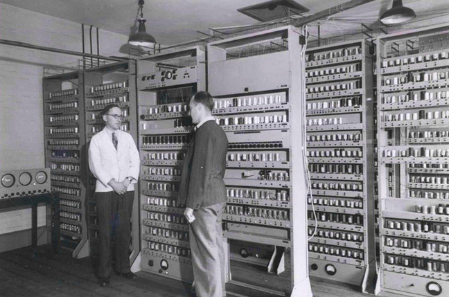
2015-06-19 U of Cambridge Computer

The University of Cambridge computer circa 1949. Back then the computer took up the whole room. It’s difficult to imagine that nowadays we have thousands of times more computing power in our pocket.
image

default

2015-06-02 Batterizer Claims 8x Battery Life

Thanks for the article, QS.  It shows a whole lot more than Batterizer’s website.  Now that I see what it looks like and how it works, I’m more convinced that it’s not snake oil.

According to the article they have been able to miniaturize the circuit.  They say the circuit has been around for awhile.  If so, it could mean that any battery operated device could have the full-size circuit added at minimal expense and the need for the batterizer would be eliminated.

I see a few other issues.

What would people do if companies stated that the use of a product such as a Batterizer would void the warranty?

My guesstimate is that more than 50% of the battery capacity is used up at the 1.3 volt point, and I’m not sure if the Batterizer will extend battery lifetime as much as 8x. My thinking is more like 2x. But that’s enough to justify the use of one.

The way a typical zinc-carbon cell works is as the cell is used, the zinc is used. With less zinc, the cell’s internal resistance goes up. At this point the cell may still have a good part of its capacity left but it cannot deliver enough power to its load because most of its power is wasted heating its internal resistance. In this case the Batterizer will not help at all. The cell may be able to run a low current load for a long time, but not a full load with or without the Batterizer. I don’t know if this same chemical action applies to alkaline cells, but if the alkaline cell’s internal resistance goes up, it will have the same problem supplying a normal load.

I’ve seen a lot of alkaline cells leak when they’re drained by a Joule Thief circuit. I think the same thing may happen with this Batterizer. You then have a damaged Batterizer and the battery holder will probably be damaged.

The circuit has no on/off switch so it draws some power all of the time it’s on the battery. Today’s chips draw very low standby current, probably in the tens of microamps, so the battery life should not be affected much by the Batterizer. But for storage or long periods of time this should be removed from the battery.

The electronic devices made today are a lot smarter than they used to be. The circuit may have a battery monitoring circuit that constantly evaluates the state of the battery. Adding the Batterizer may confuse this monitoring circuit, causing the circuit to show the wrong amount of charge left in the battery. You check, for example, to see that your camera has enough charge left, and it seems okay. But then a few minutes later your battery goes dead. There is nothing worse than missing a good photograph. So it is probably a bad idea to use the Batterizer on important things like a camera.

I’ve noticed that many, if not most of today’s battery powered equipment have a DC to DC converter, to prevent the battery’s voltage variations from affecting the circuit.  If you use the Batterizer, how is this going to affect this circuit?

Many of today’s electronic devices use the USB port to charge the batteries. Will the Batterizer confuse the charger so it gives only a partial charge? That would mean that the Batterizer can’t or shouldn’t be used on batteries that are recharged in the equipment.

Some of the equipment that I have uses a metal battery holder. The Batterizer may cause the holder to short out the battery, which can cause it to get very hot or even start a fire. This might cause very big litigation problems for the company.

There may be other factors that are detrimental to the operation of this voltage booster.

© RustyBolt.Info/wordpress
CyberChimps