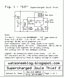
I received a a lot of comments on my Supercharged Joule Thief circuit, which gives an efficiency of up to twice that of a conventional JT (more about this in my blog where I switch between JTs and measure the light output). The SJT requires a few additional components, nothing out of the ordinary. Essentially, it rectifies some of the output to the LED, and uses this to supply the DC bias to the transistors base, through the feedback winding. I’ll post a schematic of it here.
I have built many of these SJT circuits and verified that it really does work better than a conventional JT (see the link above). The two additional parts are the 1N4148 diode and a capacitor with a value in the 470 to 1000 pF range. The cost is about $0.10 US. The resistor value of 1.5k is the optimum point between efficiency and light output. Experiment with this value to give the best choice of light output versus battery current. Higher values can give lower but adequate light output and minimize the battery current.


After all the experimenting you have done since this was first designed, do you still favour a SJT over a conventional JT routinely, or can the extra components be circumvented by a different coil design or optimised transistor specification.
I replied in my blog.
I have made this SJT and compared it to a simple JT and yes it is much better and more efficient but i noticed that the SJT would run the supply down much slower but cut out at .7-.8 V were the basic JT would keep going to .2-.4 v so actually when tested side by side the basic JT lasted longer but the SJT still had a lot more Voltage in the supply. Do you know what I can do to get the SJT to run to a lower supply?
The diode drops about 0.6 volt if it is a regular diode such as 1N4148. This adds to the startup voltage. I changed the diode to a 1N5817 Schottky diode and the voltage drip was about 0.4 volts. This reduced the problem you were talking about. If you can’t get one of these then try a 1N4002 or similar rectifier and see if it helps. It might be worse than the 1N4148.
Thanks is really helpful, I had another question about the base bias I am not educated in what it is exactly but I have read what you talked about
“The transistor’s maximum emitter to base reverse voltage is 5 or 6 volts, and the voltage will exceed this and possibly cause damage to the transistor. So the way to reduce the voltage is to reduce the number of turns of the feedback winding, or increase the number of turns of the primary winding.”
and I wanted to know how I would use the JT or SJT to power a 12v DC bulb properly without damage to transistor?
I have seen them on Youtube but after reading what you have said it seems that I could be damaging the transistor. Should I reduce the turns on the feedback wind? I currently measure the voltage I get out of my JT with a capacitor and diode connected instead of the led and I get about 70 – 80V with supply draw of 150ma supply is 2.5v because im using a Supercap in my project I am doing many different transistors and coils these numbers are just some that I have come up, by measuring the output voltage like that am I damaging the Transistor?
I thought I had replied to this, but I don’t see it.
The number of turns on the feedback winding should be 1/2 to 1/3 of the number of turns on the primary.
A 12 volt bulb has very low resistance when it is cold, and it is difficult to get a JT to start up and run. It may help to put a 1 amp rectifier between the JT and bulb, with the cathode or banded end toward the bulb.
The typical 12 volt bulb uses a lot more power than a typical JT puts out. You may not be able to get the bulb to glow very brightly.