


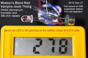
 One of the earliest germanium transistors was the 2N404. It became a popular transistor for use in projects after the demand for germanium transistors fell when Texas Instruments and other companies started selling silicon transistors (for more transistor history see here). I recently bought some germanium transistors labeled 2N404, but they seem to have much higher current gain than the original 2N404s. No matter, they make excellent vampire Joule Thiefs, because they will drain every last drop of blood.. er, juice from a battery. Here in a picture I show the LED still glowing red as the battery measures 0.278 volts. The silicon transistor JTs would have stopped working at a voltage somewhat under a half volt. Admittedly the LED is dim, but it´s still working!

2012-01-28 Blood Red Vampire Joule Thief


2012-01-27 Conventional and Supercharged Joule Thief
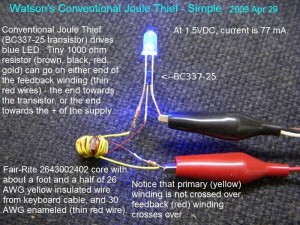
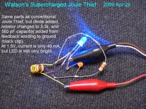 I had these pics of my JTs from 2009, both conventional and supercharged JTs. The conventional JT is lucky if it can be 50 percent efficient. My Supercharged JT will do upwards of 80 percent easily, using much less battery current while giving the same amount of light output.
I believe I have seen only one or two experimenters use my Supercharged Joule Thief circuit; for the most part it has been ignored. The circuit is almost as simple as the conventional JT. All it takes is a diode and a capacitor to make one. The diode can be a 1N914 or 1N4148, and the capacitor can be from 560 pF to 1000 pF or 1nF (ceramic disks are marked 561 or 102). The Supercharged JT picture shows how they are connected. This uses a BC337-25 transistor, but a 2N4401 or PN2222A will work fine.
Back to experimenting…
2012-01-26 Joule Thief Cost
I was reading a post from a school teacher about wanting a subject for the class project. Bingo, I thought of something that had not really come up before: “How much does it cost to make a Joule Thief?”
I guess it would be best to start with a BOM, or Bill of Materials. The prices are based on retail at an electronics store, but somet parts such as wire and batteries are not available in single quantities, you may have to buy a larger quantity.
Qty — Item Name ——————————- Cost $ (retail / large qty)
1 — LED, white or Blue ———————– 2.00 / 0.15*
1 —- Transistor, NPN PN2222A ———– 2.30 / 0.05*
1 —- Toroid, Fair-Rite 267324002 ——– 1.00 / 0.12*
2 – Wire, 24 AWG, 10 in. or 25 cm long — 1.00 / 0.30
1 — Resistor, 1000 ohms, 1/4W, 5% ——– 1.30 / 0.02*
1 — Battery holder, AA cell, with leads — 0.99 / 0.70
1 — Battery, AA cell, Alkaline pkg of 4 — 2.00 / 0.20
*The LED, transistor, resistor, toroid can be purchased in a quantity of 100 with a steep discount. For instance, if the transistor is purchased from a retail store, it may cost a dollar or more. A ‘bargain pack’ of 15 may cost $2.30 US. But if 100 are ordered from a distributor, the price per transistor may be only 5 cents or even less. The same applies to resistors and toroids.
The Coil – The coil is the more expensive part of the JT. Larger cores can cost a dollar or more apiece, but can be reused, The cores from a PC power supply can also be used, so it´s a lot cheaper if you scrounge some coils from old equipment, especially dead CFL lights. I gave the part number of a toroid available from Mouser.com. Other similar toroids are available from surplussales.com.
Wire The wire for the toroid can be bought from a home improvement / hardware store for less than a dollar a foot, but make sure it is small enough – 24 AWG or 0.5mm – so you can get about ten turns through the small core. There is speaker wire that is thin, and bell wire or thermostat wire. I’ve found that solid conductor telephone wire makes good JT coil wire. Another source for small wire is keyboard cable or similar cable – the price being free. That brings up the point that there is wire all around your. I took the bobbin out of an old table fan, and it has a lot of 28 AWG wire, useful for winding coils. The windings in motors can overheat, so make sure the wire´s enamel insulation is in good condition and does not crack when the wire is bent.
The LEDs don’t get discounted as much, but an easy way to buy a lot of bright white LEDs is to get the four pack of 9-LED flashlights on sale for under five dollars (I’ve seen them for less than four dollars US – a dollar each). That gives you 36 LEDs for about ten or fifteen cents apiece. The only problem is that they have short leads, and have to be removed from the flashlights and unsoldered from the PC board. The whole PC board with 9 LEDs can be used as it comes from the light, but it takes a lot of current to light all 9 LEDs up brightly.
The battery holder is about 70 cents apiece if ordered from a distributor in quantities of 50 or more. However some improvising can be done. I recently designed a circuit board a bit longer than AA cell, and put holes in each end to accommodate a loop of steel cut off of a paper clip. These act as a battery holder, and can be adjusted a bit for a tight fit.
Another way to hold the wires to the battery is with a magnet on each end. I soldered a small steel screw to each end of the positive and negative wires, and put some heat shrink tubing over the joint to prevent the wire from breaking. A small 1/4 inch or 6mm diameter neo magnet holds the screw to the ends of the AA cell. I obtained the small disk magnets, 1/4″ diam by 1/16″ thick from Amazingmagnets.com for $13.00 for fifty magnets (see note below).
Very strong magnets can be obtained from defective hard disk drives. They are too large for a battery but they can be broken and the pieces used. NOTE: The magnet material is very sharp, almost like glass so it poses some safety hazard. Also these magnets are very powerful and can hurt you if you get your skin between them. And if you let two magnets pull together violently, there is a good chance that one or the other will break (I’ve already had this happen).
Conclusion? When I started this blog I thought I could pin down the price pretty easily – not The problem is that there are many ways the experimenter can save, and save a lot of money. If the parts buyer is purchasing enough parts for a hundred JTs (say for a classroom project), the total price of the parts could be reduced to a fraction of retail prices. The price of 30 AWG wire is about 10 to 12 dollars US for a quarter pound roll – that will make hundreds of JTs. But just about anyone can get wire free by removing some old telephone wire from the baseboard in a room, and strip off the jacket, leaving wire that looks like new. Or take apart an old motor and unwind the wire.
The one rule that every experimenter should obey is before starting a project, obtain all of the parts. Before you pick up any tool, you should already have all of the parts.
Back to experimenting…
2012-01-25 10 Farad Powered Joule Thief Flasher
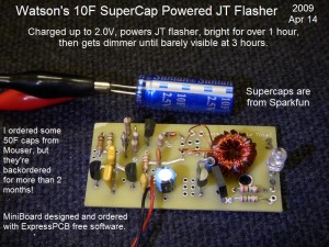 Another pic from the past – Apr 2009. The 10 Farad supercapacitor powers the flasher brightly for 1 hour and dims for another 3 hours.
The circuit consists of an astable multivibrator with unequal resistors to make it put out a short pulse every second or so. This is the three transistors to the left of the power wires. To the right of the power wires is a Joule Thief that has its 1k resistor fed by the pulses from the astable multivibrator, gating the JT on and off. The output from the JT is rectified and filtered before it gets to the LED. The extra holes in the board are for different configurations.
2012-01-24 True 2N2222 joule Thief
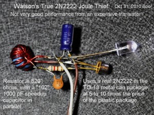 The 2N2222 and 2N2222A comes in, and has always come in a metal can package. The manufacturers came out with an equivalent that was much cheaper because it does not have the metal package, it’s a regular TO-92 epoxy package. The 2N2222 and 2N2222A specifications require a metal can package, so the manufacturers named the plastic package PN2222A or MPS2222A. I seldom see experimenters using the correct number; for some reason they can’t simply read what it says on the transistor. Duh.
Oh, I’m sorry. I forgot. The bozos at a large chain of electronic stores didn’t want people to know this so they sold bargain packs of transistors with unknown numbers as “2N2222 Type” even though the packages were plastic, not metal. It was their fault, not the poor misguided consumer.
The picture shows the true 2N2222 used in a Joule Thief. As of Feb 2012, Mouser shows the 2N2222A costs $34.40 for a bag of 100, but the PN2222A is less than a quarter of the price, $7.90 a hundred (dollars U.S.). In quantity of 100, the discount is so great that you get four times the number of the PN transistors for less than twice the price, so it really pays to buy 100.
2012-01-23 Watson’s Tiny Toroid Joule Thief
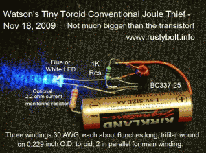 These tiny T231212T toroids from Surplussales.com are high permeability so it doesn’t take much wire to make a good Joule Thief coil. The core is less than a quarter inch diameter (here is a data sheet in .PDF.). Six inches of 30 AWG magnet wire trifilar wound, with two of the windings connected in parallel for the primary winding.
The transistor is a BC337-25. I put a 2.2 ohm resistor in series with the circuit to measure the battery current. It can be put there temporarily and removed when the LED current is what you want. How do you change the LED current? Change the 1k resistor to a different value. Higher values will reduce the LED current. With the BC337-25 and 1k resistor, the LED current should be close to 20 milliamps so it’s probably not wise to go much below 1k. If you use another transistor, especially the pipsqueak 2N3904, you may have a hard time getting it to put out 20 milliamps.
Back to experimenting…
2012-01-22 Damaschke´s Very Low V Converter
It will work with a few hundred millivolts.DAMASCHKE-064a-97ia-jmd
2012-01-21 Power Transformer for Line Operated Tube Equipment
I see a number of good designs for vacuum tube (thermionic valve) regenerative receivers in the Yahoo group Regenrx. Tubes are hard to obtain and notoriously inefficient; reasons why they would be my last choice for a receiver. But one area they have a big advantage is for use in a ham or SWL receiver connected to an antenna. When a solid state receiver is connected to an antenna, it requires a well designed protection circuit to prevent a nearby thunderstorm from damaging the sensitive transistors. A tube receiver is relatively immune from this kind of damage – tubes are very rugged and hard to damage.
But back to the receivers in the group. One schematic example can be seen here. It uses the ¨All American Five¨ set of tubes with filaments connected in series and connected directly to the AC line. This is commonly known as a Hot Chassis because of the shock and safety hazard of having the AC line voltage directly connected to the chassis. Even the antenna could become a Live Wire if the chassis is hot.
I assume that the primary reason for using this design is that a power transformer is very expensive, nowadays and in the past. I have seen power transformers selling for hundreds of dollars (US), and one for a 5 tube receiver could cost as much as a hundred dollars. I think few people know that there is an alternative that will give them a source of isolated B+ at a few tens of watts for about twenty dollars. Along with this solution, they also get a source of filament voltage that is isolated from the AC line. First off go to www.frys.com and search for power transformer. You will get a list of a few pages, and there are several choices depending on the voltage and power level you want. I chose this one because it gives over 30 watts for about 22 dollars. You need to buy two of them.
The way to connect these is as follows. One of the power transformer primary windings is connected to the AC line, through a switch and fuse of course. The second transformer´s secondary winding, in this case 18 volts AC, is connected to the first transformer´s secondary winding. The primary of the second transformer will then have the AC line voltage fully isolated from the AC line or ¨mains¨.
Let´s say the five tube radio requires 25 watts of AC power. You can connect the power plug directly to output of the above two transformers and run the radio, with no modifications whatsoever, from the fully isolated AC. If the builder wants to put this into his design, there are several other ways to run the receiver, more like one with a conventional power transformer.
Instead of using the series string filaments, the builder could use one of these transformers to furnish 6.3VAC or 12.6VAC to all of the tube filaments. The two transformers above would then be used to furnish the B+, but since the power needed would be less, a set of smaller transformers could be used. By the way, you don´t have to use one from Fry´s; these Philmore transformers and ones like them are available from other electronics dealers, Radio Shack for one (Catalog #: 273-1511).
I personally would use mostly solid state components for much of the receiver. I would then use a hollow state fire bottle (tube) for the front end that is connected to the antenna. I would get the 45 to 90 volt B+ by adding a voltage multiplier to the output of the power transformer.
One disadvantage of this arrangement is that it can take up more room on the receiver chassis. One way to reduce this is to fabricate a U shaped strap of metal and use it to mount the second transformer over the top of the first transformer. I’m sure that the builder can come up with even more ideas to keep his tube project isolated from the AC line.
2012-01-20 Wien Bridge Oscillator, Audio Generator
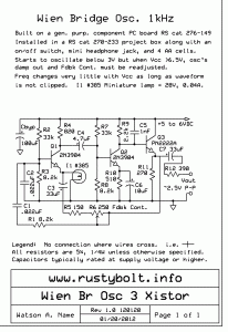
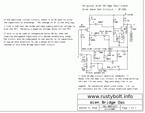 The Wien Bridge Oscillator (sometimes mistakenly misspelled Wein) uses negative feedback to generate a very pure sine wave. The circuit can generate a sine with distortion so low it is difficult to measure. The schematic I´ve attached does not necessarily have such very low distortion, but it is simple – three transistors – and generates a nice sine wave for doing audio work. You can find out how this circuit works on Wikipedia.
This circuit uses a #385 lamp in the negative feedback loop, to stabilize the oscillation point. As the output becomes greater, the higher power is fed back through R5, R6 and C3 to the lamp and it gets a little higher in resistance. The higher resistance reduces the gain of Q1 and stabilizes the oscillation point.
Nowadays with the proliferation of LEDs, lamps are getting harder to find. I have seen Chicago Miniature lamps for under a dollar in the Mouser online catalog, P. 116 (.PDF; if this has expired, go to mouser.com and search for CM385 lamp). The filament never gets hot enough to burn out so no socket is needed – just solder it in – and the lamp will never have to be replaced. You could also use the CM7009 which has wire leads.
If you don´t like to use a lamp, there is another version from a Japanese ham, JF1ozl. This uses a FET to control the feedback.
Error! This circuit is NOT a Wien Bridge Oscillator, it is a Phase Shift Oscillator.
Back to experimenting…
2012-01-19 AGC Amplifier, FET and HV Transistor
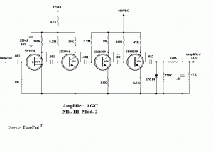 Leonard Meeks posted a schematic of Mk.7 Mod 2 AGC amplifier to the Regenrx Yahoo group. I’ll include it here.
The amp uses a FET for the input stage, a 2N3904 for the second stage of amplification and two high voltage transistors for the third and fourth stage.
For now I will talk about the 2N3904 stage, but what I say also applies to the other two transistor stages.
The base forward bias for the 2N3904 is furnished by an 8.2 megohm resistor. Assuming that the voltage across this resistor is 11 volts, the current through the resistor is about 1.34 microamps. Then assuming the current gain of the transistor is about 200, the collector current would be about 0.268 milliamps. If we multiply that current by the 39,000 ohm resistor, we get 10.45 V. Thus, there is almost 11V drop across the resistor, and the voltage at the collector is near zero. The transistor is almost into saturation and can no longer amplify. If the transistor’s gain happens to be higher, then since there is only 12V supply, the transistor will try to let as much current through the collector until the voltage across the collector to emitter is almost zero.
The beta or current gain of a transistor may be 200 at room temperature but when it is at the other extremes of temperature the gain varies widely. At cold temperatures the gain falls, and at higher temperatures the gain increases. In this case, the circuit would most likely be in a receiver that uses tubes and the temperature would most likely be higher, and the current gain would increase. Thus this circuit would greatly suffer as the temperature rises.
The text books do not recommend using this type of bias because of the disadvantages I’ve discussed. The easy way to compensate for the gain variations is to remove the top lead of the bias resistor from the supply and connect it to the collector of the transistor. As the current gain of the transistor varies, the collector voltage changes and feeds back a negative voltage to compensate. Some gain is lost, but the circuit is much more stable and less temperature sensitive. In this case, there are four stages of gain so the loss in gain would not be a problem.
I’m not sure why the author connected the second to last stage to the 100V line. The last stage should have a voltage gain of greater than 10, in which case several volts input to its base would give a full 100 volt peak to peak output. So the circuit should work just fine with the second to last stage connected to the 12V supply.
Update Jan 25 The author seems to have taken my advice and redrawn the schematic.
Update Jan 29 The author has posted a new drawing. The label is missing from the collector load resistor of the MPSA42.
The emitter or source resistors are not bypassed. This means the 2N3904 has a voltage gain of only 3 (6.8k / 2.2k). If bypass caps were added, there may be enough voltage gain that only 2 stages may be needed. But the base bias resistors don´t require an emitter resistor, so they could be zero ohms.
I had another idea. The supply voltage is very high, over 100VDC. Instead of putting the stages one after the other consecutively, this high voltage allows us to use them in a totem pole arrangement. The FET stage could be placed where the 2.2k emitter resistor is for the 2N3904. The .01 coupling capacitor would be removed from the drain and connected to ground. The 2N3094 becomes a grounded base amp. FETs are notorious for having a very wide spread of Idss, so the value of the FET´s 100 ohm resistor will have to be selected for the right drain current.
If this arrangement is used, there may be enough gain to allow two stages to do the job. In that case, the FET could replace the emitter resistor of the MPSA42.
