I got some SMT power inductors from dipmicro.com because I read that they were only 0.18 ohm and could handle almost 2 amps. The winding is on a ferrite bobbin and that is covered by a ferrite sleeve to give it a better magnetic path. But there is still an air gap between the bobbin and sleeve, which supposedly helps to store more energy (see here and scroll down to Applications). They are sealed in epoxy and have two metal ‘feet’ that are soldered to the PC board pads (no holes are needed). I had to solder two leads to them to connect it to my tack soldered circuit.
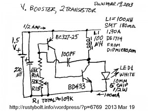
 This is a standard two transistor PNP-NPN type V boost circuit often mistakenly called a Joule Thief. I decided to use this circuit as a test circuit to try the different inductors I have purchased recently (see Note at end). This circuit had previously run on the yellow-white iron core toroids I had blogged earlier. I got better results – higher LED current – with this SMT inductor. I started with a 1000 pF capacitor but I found that the 100 pF capacitor gave more current. I also started with 68k, then added the 50k trimmer pot to adjust the base bias, and found that it had a broad peak that was a bit above 100k. Apparently the base bias controls the circuit in a way that gives a peak to the LED current.
The BD433 is a power transistor with a plastic case that is totally insulated – there is no metal for contact with a heat sink. It seems to work very well at 1.5V and high current. It must have been switching quickly on and off since there was no sign of it getting warm. I think I could put a 1k resistor from base to emitter (I’ve seen this circuit often with the resistor) and it may help a bit, without wasting much current.
Back to experimenting…
Note: I’ve been experimenting to define a standard V boost circuit that uses commonly available parts and will give a well defined performance if the experimenter sticks to the parts list. I guess one could say it will be the next best thing to buying the circuit in kit form. In this case I wanted to drive a white or blue 1 watt or more LED with a 1.5V cell, to where it will put out at least a half watt, but somewhat adjustable by the builder.


Thanks again for these wonderful circuits.
I recommend you to use any schematic drawing software so that the circuits are more clear. I do not mean they are unclear but just an advice.
Thanks for the info. 🙂
I was using ExpressSCH, a part of the free software ExpressPCB, which is only available for Windows. Now I am using Linux and it’s not available for Linux – in the meantime I’m drawing them manually. I installed Kicad, but I just started using it this week, and it’s going to be awhile before I’m up to speed. I tried getting on their website and got a 504 error message. Some of my older blogs have the schematics in ExpressSCH. Also I posted over 150 of of my schematics to watsonspics.blogspot.com.
Hi, I’ve designed the equivalent of a 1000 watt light, that only uses about 35 watts, and pulls a little under 3A. http://www.youtube.com/watch?v=URsHTxQlG1k
It also put out minimal heat. By minimal, I mean you can put you can put your hand on, and not get burned, even if it’s be on for over half an hour. The distance from my front porch to where I illuminated the side of my apartment complex is 50′. At that distance, I was still getting between 3-4 lux on my meter. It use 12 volts.
Now here is where I’m thinking waaay out of the box, I want to use 350F Supercaps @ 2.7V, and 0.35Wh, instead of batteries, and your circuit looks the most promising.
To be honest, six months ago I could not read a schematic, and at this moment I am kinda teaching myself Electrical Engineering on the fly. The main reason I am able to do this is because I am also Bipolar II, or as some call it Bipolar lite. So as you can tell, I’m the kind of person, who would be fighting windmills! lol
Any thoughts on this would be much appreciated. Thank you,
Danny
I just started a blog for you about this subject, rather than bury it in a comment.
http://rustybolt.info/wordpress/?p=8368